|
Author
|
Topic: My personal Apollo story (Dan Schaiewitz)
|
mikepf
Member Posts: 448
From: San Jose, California, USA
Registered: Mar 2002
|
 posted 09-02-2016 11:44 AM
   
quote:
Originally posted by Daniel on the Moon:
How many of you are under the impression that EVA "training" PLSSs and OPSs were flight configured units that were downgraded (Class 111) for EVA crew training?
Sorry I'm late with my reply to your question. To answer you, I really don't know, but look forward to you educating me. |
jklier
Member Posts: 91
From: Austin, Texas
Registered: Aug 2007
|
posted 09-06-2016 11:03 AM
Daniel, I have to say this is one of the most enjoyable threads I've read on this site. Thank you so much for taking the time to post.I'm curious if you ever worked with this piece of hardware? This one is going for auction and the other is at the Smithsonian. If you worked with it can you share a little on that experience? |
carmelo
Member Posts: 1109
From: Messina, Sicilia, Italia
Registered: Jun 2004
|
posted 09-08-2016 09:12 AM
Dan you have wear Apollo spacesuit and suit and PLSS inside mock up of Apollo command module and lunar module (see this thread)? |
Daniel on the Moon
Member Posts: 354
From: Bronxville, NY
Registered: Jun 2015
|
posted 09-10-2016 11:43 AM
quote:
Originally posted by jklier:
I'm curious if you ever worked with this robot
The subject robot was used at MSC from 1963 to 1965 when the project was discontinued. I arrived at KSC to begin my "dream" in 1968. |
Daniel on the Moon
Member Posts: 354
From: Bronxville, NY
Registered: Jun 2015
|
posted 09-10-2016 12:14 PM
quote:
Originally posted by carmelo:
Dan you have wear Apollo spacesuit and suit and PLSS inside mock up of Apollo command module and lunar module?
I was not involved with any CM inside operations. I was inside the LM mockup on various occasions evaluating Pre and Post EMU donning and doffing procedures, PLSS recharge procedures (Feedwater and Oxygen recharge, LIOH canister replacement), etc.However, I donned my PGA before entering the LM (up to PGA "zip up") and doffed the PGA after LM ladder descent. Believe me, it was "cramped". I always wondered how much easier it was in zero "G"! |
ejectr
Member Posts: 2025
From: Killingly, CT
Registered: Mar 2002
|
posted 10-13-2016 10:37 AM
Miss your stories, Dan. Hope all is OK... |
Daniel on the Moon
Member Posts: 354
From: Bronxville, NY
Registered: Jun 2015
|
posted 10-13-2016 08:22 PM
Thank you for your concern. I will be back soon. I'm looking forward to continuing posting my Apollo Program experiences to interested cS members. |
SpaceyInMN
Member Posts: 367
From: Andover, MN
Registered: Dec 2013
|
posted 10-14-2016 02:49 AM
I look forward to your return, Dan. I was also starting to wonder where you had gone. |
ejectr
Member Posts: 2025
From: Killingly, CT
Registered: Mar 2002
|
posted 10-14-2016 02:11 PM
Great to hear from you and I'm looking forward to more of what you know and experienced. |
NJ CO
Member Posts: 23
From: Greenwich, NJ, US
Registered: Mar 2008
|
posted 10-14-2016 07:14 PM
All the best, Dan. As always, many thanks for your generous time in your reflections and insights. |
Daniel on the Moon
Member Posts: 354
From: Bronxville, NY
Registered: Jun 2015
|
posted 10-14-2016 09:59 PM
Thank you. |
Daniel on the Moon
Member Posts: 354
From: Bronxville, NY
Registered: Jun 2015
|
posted 11-03-2016 01:30 AM
Please reference the following photos when reading the below post.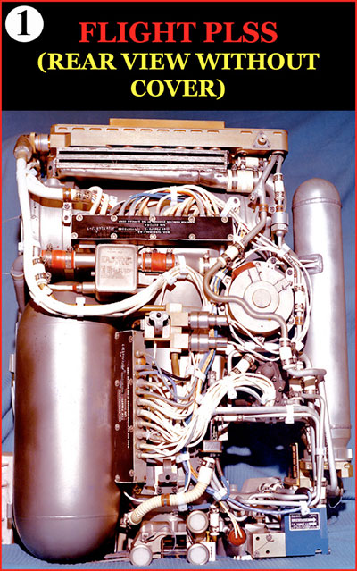 
My responsibilities as Apollo PLSS/OPS KSC EVA Crew Training Mission Manager began with a memo from MSC Crew Systems Division stating that the remaining Apollo 11 and all future mission EVA crew training exercises would be conducted at KSC and all EMU training hardware (suits, PLSS/OPSs, and supporting hardware) would be shipped to KSC in time for a June 6, 1969 KSC training exercise.
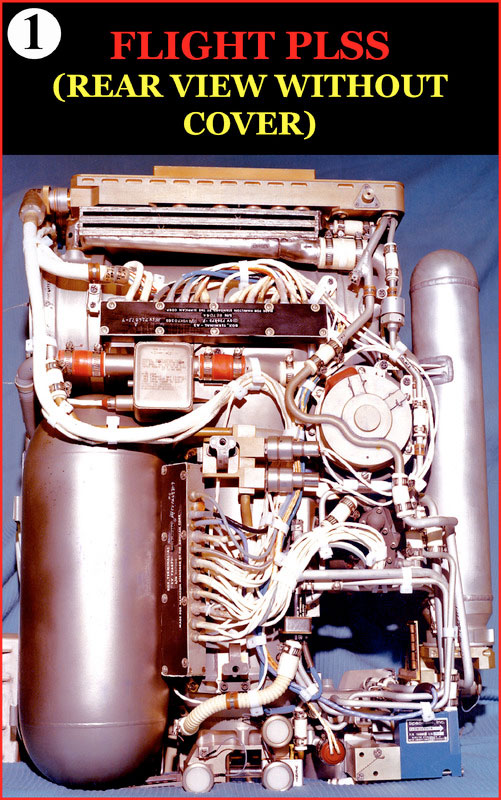
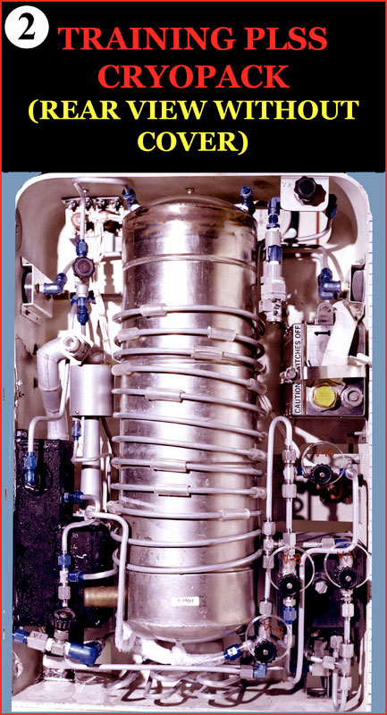
PLSS/OPS crew training hardware had already been designed and fabricated and was being used at MSC for Apollo 11 and preliminary Apollo 12 EVA Training. The PLSS/OPS training hardware that we received from MSC to support KSC EVA training was, contrary to popular belief, totally functionally different than the flight PLSS/OPS whereas the training suits were flight configured and downgraded to training status. Let me repeat and this is very important, The PLSS/OPS training hardware was totally functionally different from PLSS/OPS flight configured hardware. My experiences and the decisions I had to make (as Apollo PLSS/OPS KSC EVA Crew Training Mission Manager) as a result of maintaining and managing PLSS/OPS EMU training hardware that did not perform as expected will be the basis of most of my future cS posts. It is a story that was never documented and in the interest of preserving and documenting a very important aspect of the "Apollo Story" for future historians I feel it is my obligation to document my experiences and the decisions I had to make. Before I became involved with the PLSS/OPS training units, my work at KSC was with the Flight PLSS/OPS hardware. Because of my intimate knowledge of the flight hardware and my extreme enthusiasm about my work (my dream job), my request to be assigned PLSS/OPS Crew Training Mission Manager was granted (one of the many highlights of my Apollo experience). I realized that I now had to familiarize myself with a totally new system both from a functional and procedural standpoint and concurrently continue my responsibilities as a KSC HSD engineer. Knowing the frantic pace at which Apollo schedules were moving forward I anticipated that my upcoming new responsibilities were going to be very challenging. As I previously mentioned, the training PLSS Cryopack and OPS were totally functionally different from the flight configured PLSS/OPS. The flight PLSS/OPS was designed and built to function on the moon, not on earth. All components were, of course, designed with that in mind. Many of you know that suit ventilation cooling and body cooling (using the Liquid Cooling Garment, LCG) were accomplished through the process of sublimation, a process that only works in the vacuum of space using the PLSS sublimator that allowed ice to change from its solid state to a gas skipping the liquid phase. All other components were also specifically designed and optimized to function on the moon. The PLSS was a fully autonomous system when used for its intended purpose on the moon. The PLSS controlled suit pressure, provided up to eight (8) hours of breathable oxygen, removed exhaled carbon dioxide, removed particulates and odors, provided body and ventilation cooling, controlled humidity and provided voice and telemetry communications. Not only was the PLSS non earth function issue a reason for designing an earth training PLSS/OPS but also the weight of the flight PLSS/OPS would have been an issue as the flight PLSS/OPS weighed 125lbs (PLSS - 84lbs, OPS - 41lbs). With the suit at 60 lbs, a total of 180 lbs would have been a serious issue for the crew magnified even more on the simulated lunar surface outside the crew training building in the heat of the spring, summer and fall Florida sun. The weight issue was not completely resolved since the final weight of the Cryopack, OPS and suit was 130lbs (Cryopack - 60lbs, OPS - 10.5lbs, Suit - 60lbs). The weight difference of 49.5lbs however was offset by the lack of Cryopack LCG water cooling capability until the beginning of Apollo 16 crew training when I was given authority to fabricate a make shift cooling device that I and one of my crew training techs designed (details will be included in a future post). Using the flight PLSS carbon dioxide and odor removal capability would have also been unfeasible as the PLSS Lithium Hydroxide Cartridge was a one time use component and it would have been cost prohibitive to provide new cartridges for every crew training exercise. My impression when I first compared the flight PLSS (Photo 1) to the training PLSS Cryopack (Photo 2) was one of questionable belief or perhaps disbelief. What I saw when looking at the Cryopack was hardware that might have been built in someone's garage! In retrospect, comparing the Cryopack to the flight PLSS that I had lived with day in and day out and labeling it as "garage built" may have been a little too harsh. However, as you will see in future posts, my initial observation may not have been too far off! |
Jeff
Member Posts: 623
From: Fayetteville, NC. USA
Registered: May 2009
|
posted 11-03-2016 06:56 AM
Always interested in your first hand experiences. Welcome Back Dan. |
jasonelam
Member Posts: 695
From: Greensburg, KY USA
Registered: Mar 2007
|
posted 11-03-2016 09:15 AM
Thank you, Dan, for explaining the difference between a flight and training PLSS. It really gives a better understanding of what was really happening to train the men who walked on the moon. |
oly
Member Posts: 1484
From: Perth, Western Australia
Registered: Apr 2015
|
posted 11-03-2016 09:36 AM
Many thanks Dan. |
MCroft04
Member Posts: 1861
From: Smithfield, Me, USA
Registered: Mar 2005
|
posted 11-03-2016 10:23 AM
Were the flight PLSS/OPS tested in the vacuum chamber prior to launch? If so can you share who tested them and how it was done? |
Kite
Member Posts: 1163
From: Northampton UK
Registered: Nov 2009
|
posted 11-03-2016 12:42 PM
Thanks Dan. Your posts are so informative and understandable, made by someone who was actually there is brilliant. What a responsibility you had. We are so much obliged to you on cS. |
Daniel on the Moon
Member Posts: 354
From: Bronxville, NY
Registered: Jun 2015
|
posted 11-03-2016 01:56 PM
quote:
Originally posted by MCroft04:
Were the flight PLSS/OPS tested in the vacuum chamber prior to launch? If so can you share who tested them and how it was done?
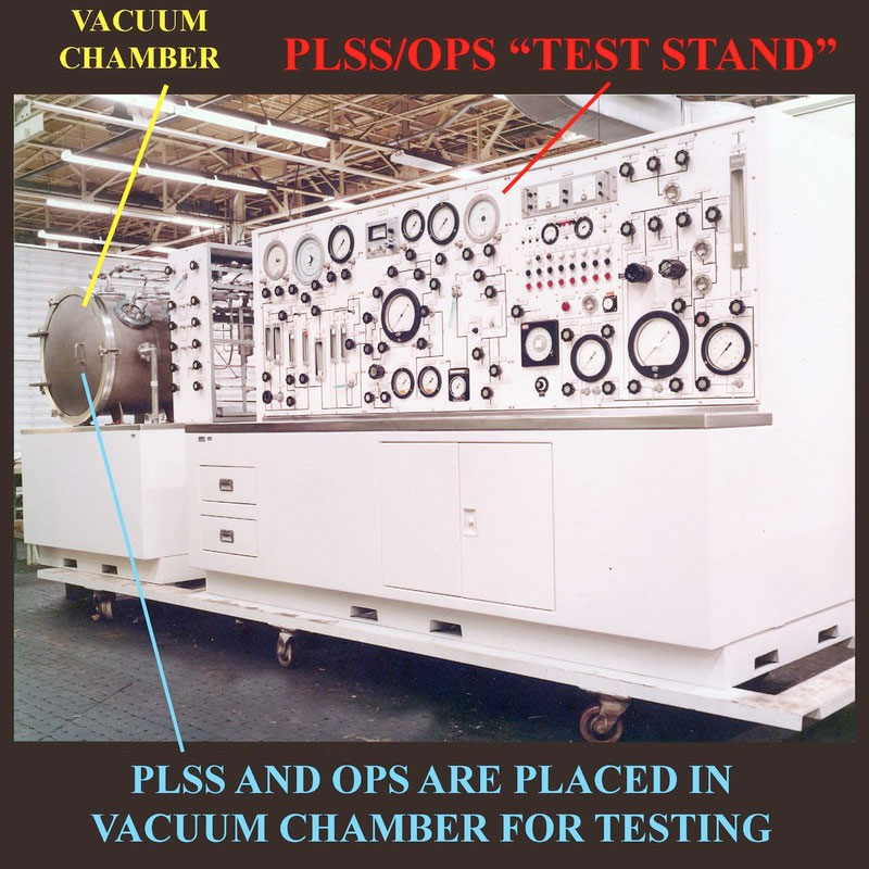
The answer to your question is yes. All flight designated PLSS/OPSs including the PLSS Remote Control Unit (RCU) were tested in the Hamilton Standard "clean room" at KSC. In addition, there were designated "backup" flight PLSS/OPS units that were also tested prior to mission launch.Time constraints, especially a few weeks before launch, resulted in testing the flight and backup flight units, for most missions, beginning about three weeks before launch. The pre-flight tests were called "Pre-Installation Acceptance" (PIA) testing. I'll take you through a brief summary of the testing as you requested using as an example Apollo 11 flight and backup PLSS testing. As LM-5 PLSS/OPS Mission Manager, I was very fortunate to have been the responsible HSD engineer for conducting the PLSS "Pre-Installation Acceptance" (PIA) testing for both Armstrong's and Aldrin's flight and backup PLSS/OPSs. The testing began on June 23, 1969 and was completed on July 10, 1969, just six days before Apollo 11 liftoff (July 16, 1969). The procedures that all contractors had to follow with respect to conducting tests were as follows: First, a "Test Preparation Sheet" (TPS) was written to authorize the testing. Then, a "Test and Checkout Procedure" (TCP) was written to include the specific procedures used to conduct the test, i.e. how a specific components function was to be evaluated using the Clean Room Test Facility. All of the PLSS system, sub-system, and component testing was performed using the above referenced HSD Test Facility and as we called it, the "PLSS/OPS Test Stand" (below photo). The Test Stand included a vacuum chamber that simulated the vacuum of space and provided the capability of testing the performance (function) requirements that the PLSS/OPS and its components were designed for.The PLSS and OPS were, of course, tested separately using separate Test and Checkout procedures (TCP). 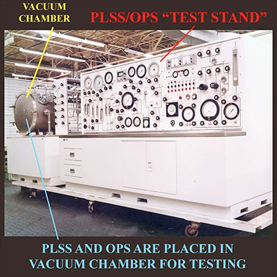 As the contractor engineer in charge of the test, I read each line of each procedure to the HSD technician who turned the dials, pushed the switches, read the gauges, etc. After each test procedure, if the PLSS subsystem, component, etc. performed within test specifications, both the HSD Quality Control inspector and a NASA Quality Control inspector placed an approval stamp next to the procedure in the TCP. If, during the execution of testing, there was an undiagnosed issue, an "Interim Discrepancy Report" (IDR) was written and logged in a "Test and Inspection Record" (TAIR) book without stopping the test. Following the completion of the test, the IDR would be further investigated and dispositioned as either resolved or up-graded to a "Discrepancy Report" (DR).
A DR was written by the contractor (HSD) QC inspector for any out of specification test results. The DRs were entered into the TAIR book. DRs remained open until they were dispositioned and signed by the test engineer (me) and a NASA contractor engineer liaison that was permanently assigned to the contractor. The PLSS Flight Approval Document was the actual Test Checkout Procedure (TCP) that included the HSD and NASA Quality Control approval stamps and my signature as Test Engineer Conductor. |
Daniel on the Moon
Member Posts: 354
From: Bronxville, NY
Registered: Jun 2015
|
posted 11-03-2016 04:13 PM
quote:
Originally posted by Jeff:
Always interested in your first hand experiences.
Thanks Jeff for your continued support. Great hearing from you. |
Daniel on the Moon
Member Posts: 354
From: Bronxville, NY
Registered: Jun 2015
|
posted 11-03-2016 04:26 PM
quote:
Originally posted by jasonelam:
Thank you, Dan, for explaining the difference between a flight and training PLSS.
Thank you for taking the time to read my lengthy post. Stay tuned for future posts describing in detail the effort required to make sure that every mission scheduled EVA crew training exercise was accomplished as planned, on time without real time EMU hardware issues. |
Daniel on the Moon
Member Posts: 354
From: Bronxville, NY
Registered: Jun 2015
|
posted 11-03-2016 04:34 PM
quote:
Originally posted by Kite:
What a responsibility you had. We are so much obliged to you on cS.
More thanks to you and other cS members that have similar interest in Apollo. Before I joined cS, I had no idea there existed people with similar passion for the most technological achievement accomplished by mankind. |
Jurg Bolli
Member Posts: 1243
From: Albuquerque, NM
Registered: Nov 2000
|
posted 11-03-2016 06:58 PM
Daniel, you got it right: "...most technological achievement accomplished by mankind." Great information, thanks. |
MCroft04
Member Posts: 1861
From: Smithfield, Me, USA
Registered: Mar 2005
|
posted 11-04-2016 10:38 AM
Dan, thanks for the clarification on this very interesting and important part of the success of the lunar program. How much time did the astronauts have with the flight PLSS prior to launch? I realize it was too heavy for them to train with, but it seems like they would have wanted to at least see the flight item before they had to use it on the moon. |
Daniel on the Moon
Member Posts: 354
From: Bronxville, NY
Registered: Jun 2015
|
posted 11-04-2016 11:27 PM
Prime crews for all missions did have a chance to work with the flight hardware about three weeks before liftoff. The procedure for Apollo 11 was named the EMU Final Donning Procedure Verification. For future missions the procedure was called the Final Crew Fit and Function Test.The purpose of the procedure was to: - Verify in flight EMU donning and checkout procedures.
- Provide the crew with a final look at the flight EMU hardware.
- Familiarize the crew with recent changes to flight hardware that might have been made.
- Provide an opportunity to resolve any open questions or items of crew interest.
Please note that the astronauts were very familiar with flight hardware configuration since they practiced using "mockup" PLSS/OPSs quite a few times during EVA donning and doffing exercises. I should note that it was my responsibility to make sure the PLSS/OPS mockups were continually updated as a result of flight hardware configuration changes.The mockup PLSS/OPSs should not be confused with the the PLSS cryopack that was used for EMU lunar surface training as I discussed in a recent post. |
ejectr
Member Posts: 2025
From: Killingly, CT
Registered: Mar 2002
|
posted 11-05-2016 06:44 PM
I'm glad you found this site. Your stories and relations of the equipment and the people are impeccable. I'm sure to not miss any of your first hand accounts.This first hand information is priceless. Thanks, Dan. |
Daniel on the Moon
Member Posts: 354
From: Bronxville, NY
Registered: Jun 2015
|
posted 11-05-2016 11:04 PM
Thank you for reading my posts and thank you for your kind comments.As we all know, one of the normal signs of aging is memory loss. At 73, there are quite a few past events and parts about my life that I have difficulty recalling. However, memories of my Apollo experiences are so vivid and I so much enjoy digging back into the far reaches of my brain to relate the most incredible part of my life. |
Mike Dixon
Member Posts: 1625
From: Kew, Victoria, Australia
Registered: May 2003
|
posted 11-06-2016 03:04 AM
May we all be blessed as you have been to recount in so much detail, the events (sadly) now so far in the past. I have learned a LOT and for that, my thanks mate. |
ejectr
Member Posts: 2025
From: Killingly, CT
Registered: Mar 2002
|
posted 11-06-2016 01:06 PM
You just keep remembering and talking, Dan. I, for one, am forever listening, not only to the subject matter but more importantly, to someone that was there and experienced all of what he is saying.I'll gladly wait for the things you have to think about to remember... and I'm certain you will. As I said, you are a treasure trove for us and may you always have more to tell us. |
Daniel on the Moon
Member Posts: 354
From: Bronxville, NY
Registered: Jun 2015
|
posted 11-07-2016 05:05 PM
In a previous post, I established that the PLSS/OPS training hardware was totally functionally different from PLSS/OPS flight hardware. I also provided rationale why the flight PLSS/OPS could not be used as a 1-G training option.
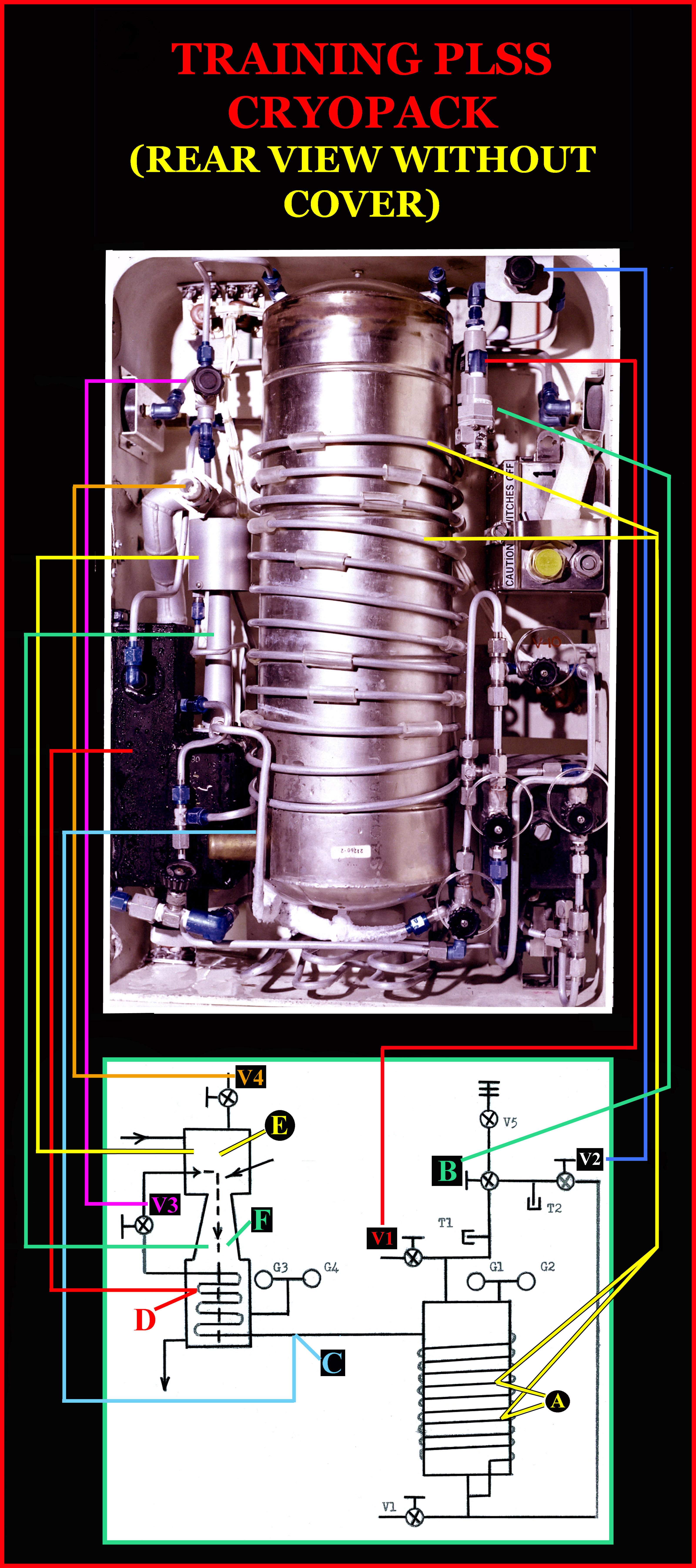
When the PLSS cryopacks were received at KSC from MSC on June 4, 1969, they were accompanied by an MSC HSD technician whose responsibility was to provide myself and two HSD KSC techs the necessary information required to understand the "function" and "procedural use" of the cryopacks in time for a June 6 EVA training exercise at KSC.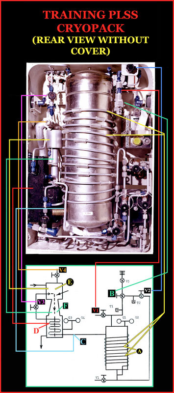 Cryopack functional orientation: The cryopack provides pressurization and ventilation to the astronaut during Lunar Surface EVA crew training exercises. Liquid Air is utilized to accomplish the required objectives. Liquid Air is air that has been cooled to less than -221.26℉ so that it condenses into a pale blue liquid. To protect the Liquid Air from reverting back to its gaseous state before it is functionally utilized (liquid air can absorb heat rapidly and revert back to its gaseous state), it is stored in a vacuum insulated container. In the case of the Cryopack, the insulated container is cylindrical as seen in the above photo. The Cryopack operates as follows (refer to above photo): After the pack is filled (with Liquid Air), Vent Valve (V-1) is closed and Pressure Buildup Valve (V-2) is opened. This allows the liquid air to enter the Build Up Coil (A), vaporize and pressurize the Dewar to 140±3 psig at which time the Pressure Regulation Valve (B) closes and stops flow into the Build Up Coil (A). The Pressure Regulation Valve (B) then modulates between open and closed to maintain system pressure. Opening Supply Shutoff Valve (V-3) allows system pressure in top of the Dewar to force liquid air from the bottom of the Dewar into Supply Line (C). The Liquid Air then passes through Heat Exchange Coils (D) to ensure complete vaporization before entering and exiting an Ejector (E) as a high velocity stream of gas. The ejected gas directed into Venturi (F) induces ventilation flow to the Suit Inlet Hose. A sufficient amount of gas is "dumped" out of the Suit Purge Valve (located in the suit exhaust line) to maintain CO2 levels below 7.6 mm Hg. A Suit Pressure Valve (V-4) is used to pressurize the suit to 3.75 psi. System Pressure and Suit Pressure are monitored on duplicate gauges on both sides of the Cryopack. Cooling from the ventilation gas provided heat removal up to 1200 btu/hour. The Cryopack was designed to operate for 1.5 hours. |
MCroft04
Member Posts: 1861
From: Smithfield, Me, USA
Registered: Mar 2005
|
posted 11-07-2016 05:27 PM
OK, how many of you got that on the first read? Be honest! |
ejectr
Member Posts: 2025
From: Killingly, CT
Registered: Mar 2002
|
posted 11-07-2016 06:00 PM
Got it... Never thought I'd even get to hear about this. Never mind an in depth explanation. Thanks Dan... |
Rusty53
Member Posts: 50
From: Rochester, NY USA
Registered: Jun 2010
|
posted 11-07-2016 07:16 PM
Dan, thanks for such a great tutorial on the workings of the cryo-pack. As I read your very detailed description and view the schematic diagram, I notice that there are two V3 valves and one of them appears to be the V2 valve in the picture. I am probably missing something obvious, because I am certainly no engineer! |
Daniel on the Moon
Member Posts: 354
From: Bronxville, NY
Registered: Jun 2015
|
posted 11-07-2016 08:28 PM
I'd like to say that I purposely labeled two V3 valves to find out who actually read the post as you did. However, I did in fact incorrectly label one of the V3 valves that should have been labeled V2.The photo has been corrected. Thank you for taking the time to read my post and finding my typo. |
ejectr
Member Posts: 2025
From: Killingly, CT
Registered: Mar 2002
|
posted 11-08-2016 03:38 PM
In some schematics, a part or, in this case, a valve may be labeled the same thing because there are two parts to the same valve being used in two different places to save room. This is what I thought when I saw it. This is what I've come to experience in Computer Numerical Control machinery. I didn't think there was anything other than that involved. |
LM-12
Member Posts: 4021
From: Ontario, Canada
Registered: Oct 2010
|
posted 11-13-2016 01:40 PM
What are the two PLSS-related fixtures seen in the LM near the tunnel in photo AS13-62-8935?
|
Daniel on the Moon
Member Posts: 354
From: Bronxville, NY
Registered: Jun 2015
|
posted 11-13-2016 05:18 PM
Please reference the following Figure 1: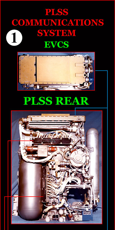
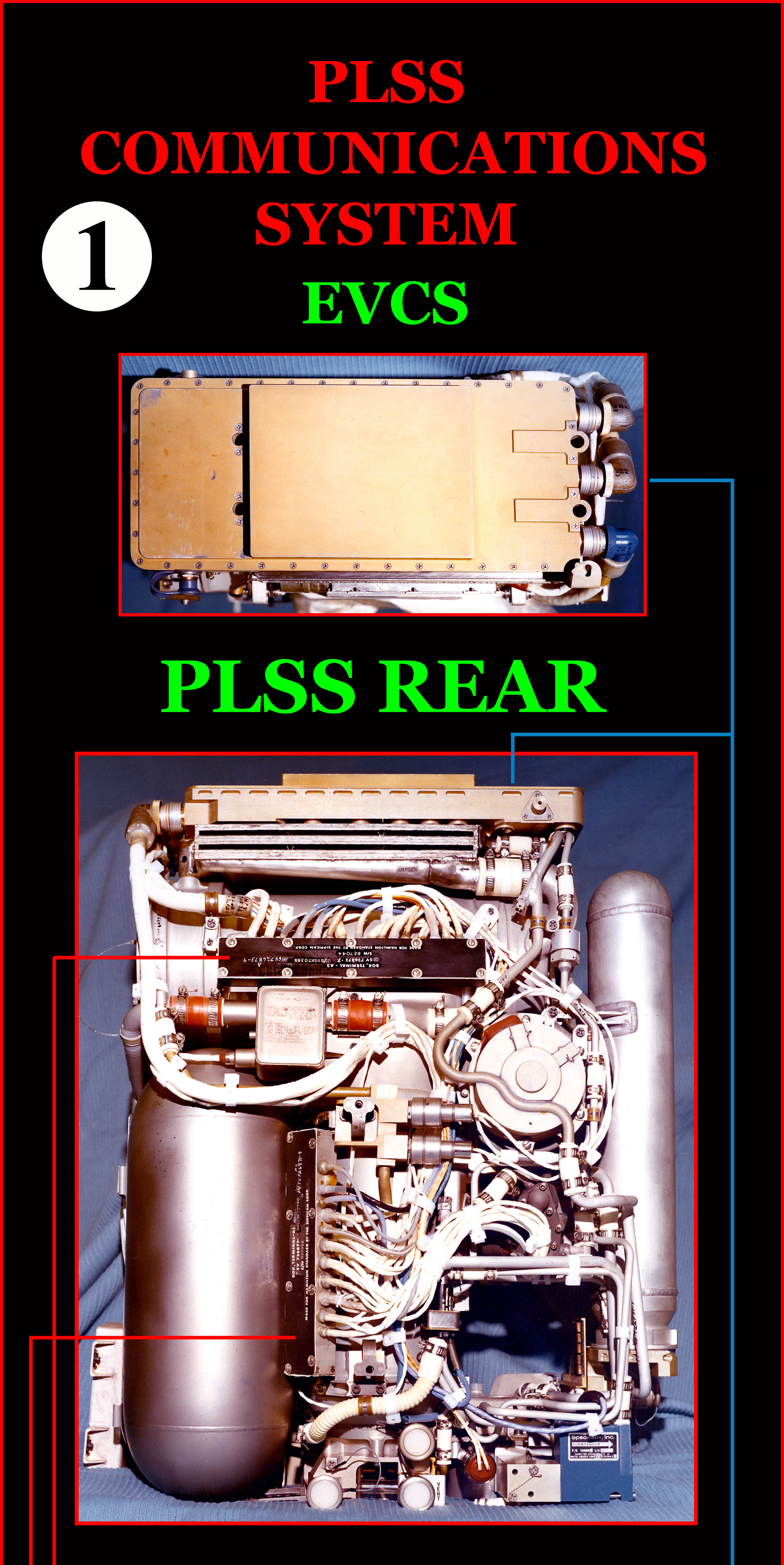
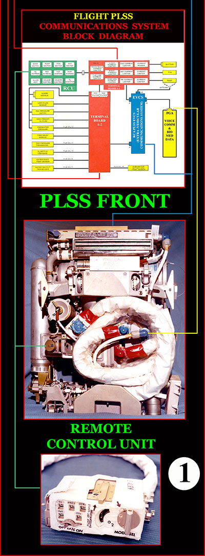 As I previously discussed and emphasized, the training PLSS Cryopack was totally functionally different from the flight configured PLSS. I covered differences between the flight PLSS and Cryopack Suit Ventilation, Suit Pressurization and Suit Cooling capabilities. Differences between the flight PLSS/OPS and training PLSS Cryopack Communications System have not yet been addressed. To that end, I will, in this and one or two subsequent posts, discuss PLSS and Cryopack Communications System differences. First let's take a look at the flight PLSS Communications System referred to as the Extra Vehicular Communications System (EVCS). In Figure 1 above, I "attempted" to relate EVCS Block Diagram components to corresponding components in front and rear photos of the PLSS and the PLSS Remote Control Unit (RCU).
The EVCS, manufactured by RCA, accomplished three major communications objectives as follows: - Provide primary and backup Dual Voice Transmission and Reception between earth and moon.
- Provide Telemetry Transmission of Physiological (Bio-Medical) data to earth.
- Provide Telemetry Transmission of PLSS Performance (Function) data to earth.
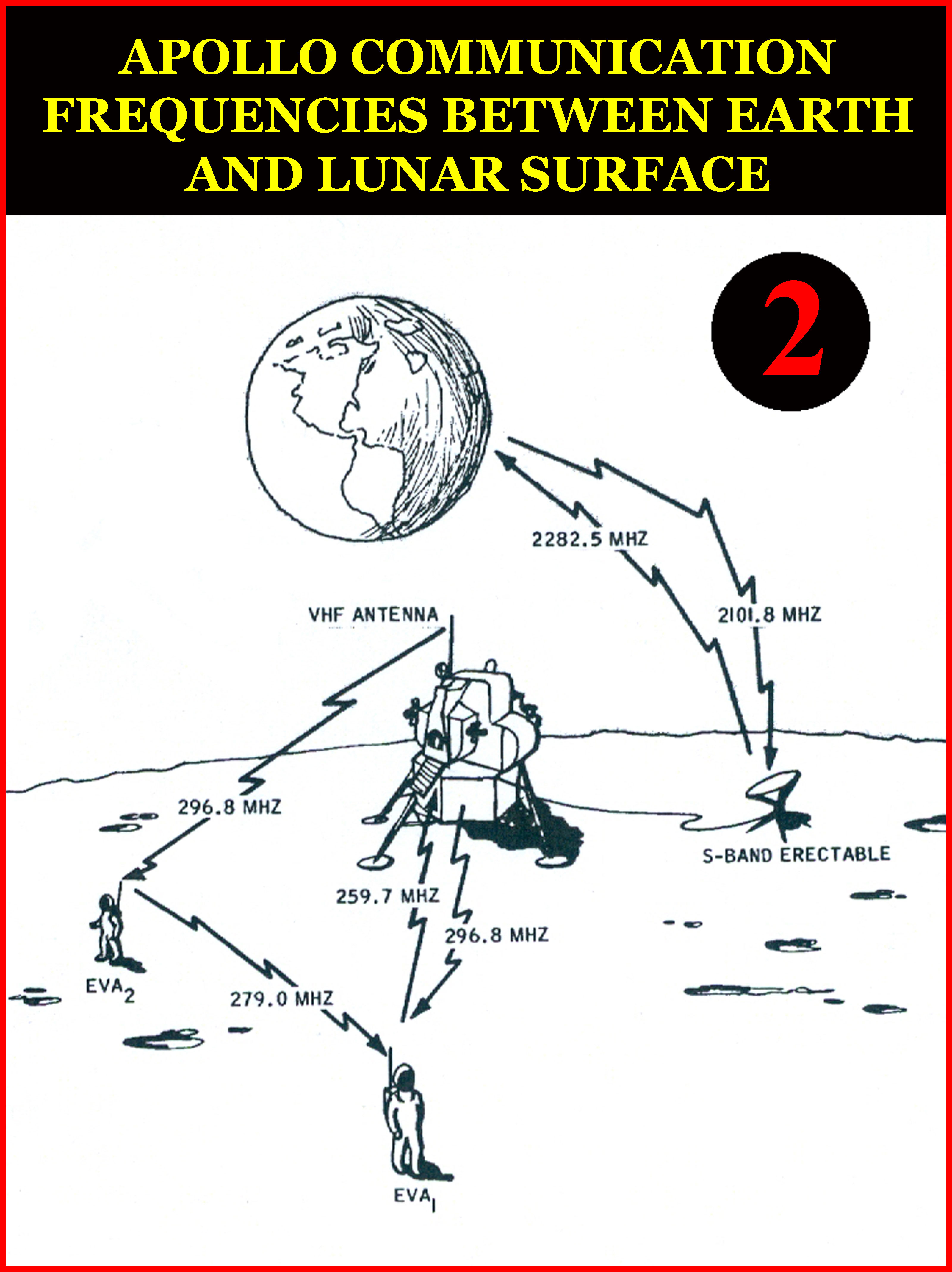
As the bullet points indicate above, the EVCS provided primary and backup dual voice transmission and reception, telemetry transmission of astronaut physiological and PLSS performance data. The EVCS also regulated voltage and electrical current of PLSS operational sensors (transducers). Operation of the communication system in the dual mode provided crew members with uninterrupted duplex voice communications with one another, with the LM and, via the LM through a crew erected S-Band antenna to Mission Control. Telemetry information was transmitted without interrupting or interfering with voice communications.Nine telemetry channels transmitted to the LM carried PLSS and suit operational data. A tenth TM channel transmitted crewman electrocardiogram (ECG) data. Indicators mounted on the remote control unit (RCU photo in Figure 1) provided the astronaut with a visual warning of high oxygen usage rate, low suit pressure, low ventilation flow, low water pressure and high CO2 levels (Note the block diagram in Figure 1 does not include CO2 sensor monitoring as CO2 level monitoring was added later in the program) . When an abnormal (out of specification) condition existed, an audible tone sounded in the astronaut communications carrier (Snoopy headset). The audible tone alerted the crewmember to look down at his Remote Control Unit (RCU) to find the specific abnormal condition(s) defined by specific visual notification that appeared in RCU indicator windows, identifying the problem so that the astronaut was able to take corrective action. Voice and telemetry communications was sent and received on three frequencies between the crewman and the LM. It is my understanding (correct me if I am wrong) that the astronauts communicated with each other via 279.0 MHZ. Voice communications from LM to the crew utilized 296.8 MHZ. Voice and data from the crew to the LM utilized 259.7 MHZ, however, voice and data from EVCS 2 (LMP) had to be transmitted to EVCS 1 (CDR) and then voice and TM from both crewman were transmitted to the LM through EVCS 1. Note that other optional communications modes were available (utilizing the RCU mode selector switch) if anomalies occurred. Voice and TM data was transmitted from the LM to earth via the aforementioned S-Band antenna erected by the astronauts using frequency 2282.5 MHZ. Voice from earth to the S-Band antenna was relayed via 2101.8 MHZ. The below Figure 2 may help decipher my possibly incoherent explanation.  It is obvious that the EVCS was a technological marvel for its time. I stated at the beginning of this post that I will compare the flight PLSS EVCS to the Cryopack EVCS. What if I told you that the Cryopack EVCS hardware was identical to the PLSS EVCS! Yes, however, the capabilities of the EVCS were only partially utilized when used with the Cryopack for EMU training. Stay tuned for my next post. |
Daniel on the Moon
Member Posts: 354
From: Bronxville, NY
Registered: Jun 2015
|
posted 11-14-2016 01:38 PM
quote:
Originally posted by LM-12:
What are the two PLSS-related fixtures seen in the LM near the tunnel in photo AS13-62-8935?
Are you referring to the two PLSS Donning Station Fittings? If so, I am not familiar with them. There was no point in PLSS donning procedures that I was involved in that had anything to do with donning station fittings.Perhaps the following from the Apollo 15 final report (referring to vertical PLSS straps going up to the cabin fitting) is a clue! If you're not careful with the vertical straps going up to the cabin fitting, you can put extra stress on that PLSS mounting; also, the interface of the straps could take off the thermal cover of the PLSS. IRWIN The straps on the Commander's side occasionally bear down on the Y-adapter and also the PLSS hard line. We should look a closer look at it. We should look strongly at some other way of securing the PLSS. Let me know if you find a definitive answer. |
Daniel on the Moon
Member Posts: 354
From: Bronxville, NY
Registered: Jun 2015
|
posted 11-14-2016 10:33 PM
Refer to below Figure 3: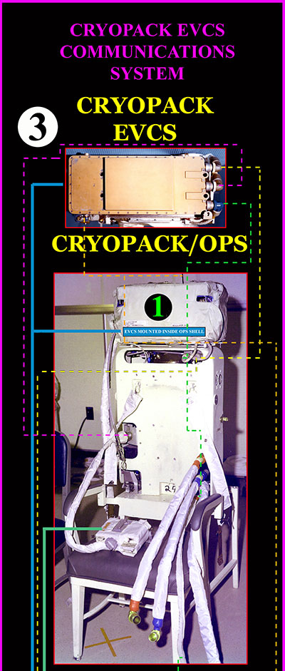
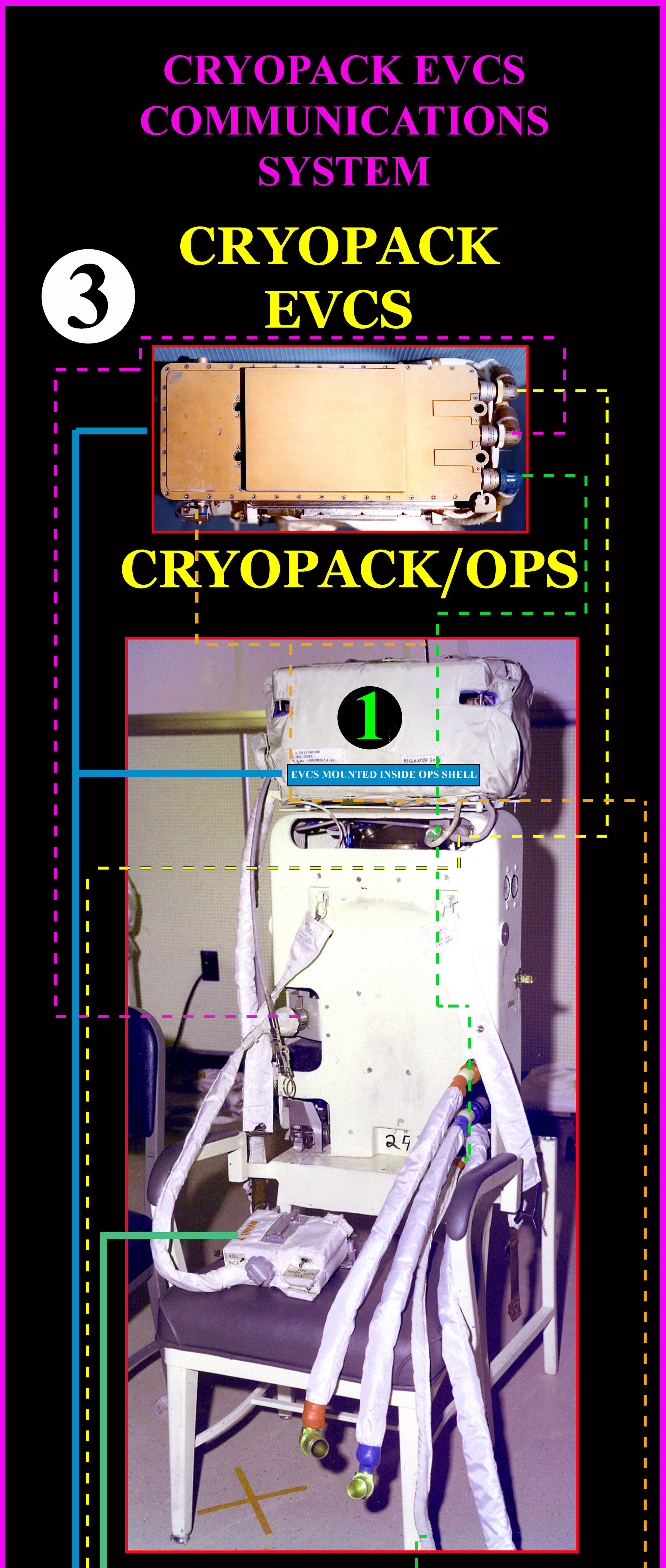
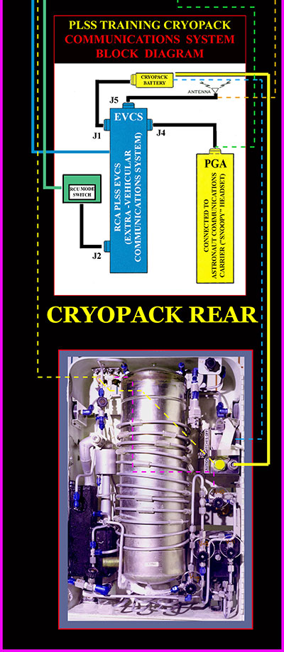 In my last post, I documented the operational functions of the flight PLSS Communications System (EVCS). As a reminder, the PLSS EVCS was utilized to provide voice communications and telemetry data for both astronaut bio-medical and PLSS operational data. I also mentioned that the Cryopack EVCS hardware was identical to the PLSS EVCS! However, the capabilities of the EVCS were only partially utilized when used with the Cryopack for EVA training. Specifically, communications using the Cryopack EVCS was used for voice communications only. TM data transmission from the training PLSS Cryopack was not needed as there were no transducers in the Cryopack to monitor and send performance data and it was deemed not necessary to monitor astronaut ECG data. The thinking was that the close contact between crew members, techs and myself would allow us to visually recognize astronaut life threatening situations. The training EVCS was mounted inside an OPS shell (Figure 3, #1) as there was no need for a working emergency oxygen system. The above Figure 3 Cryopack communications Block Diagram shows EVCS connector "J4" connected to the PGA electrical umbilical connector in turn connected internally to the astronaut communications headset. EVCS "J5" connector is connected to the EVCS antenna mounted on top of the (OPS). EVCS "J1" connector was connected to a battery inside the Cryopack providing the EVCS with its power source. EVCS "J2" connector was connected to the PLSS RCU. Since there was no telemetry data, the only function of the RCU was to turn on EVCS voice communications by pushing the RCU "Push To Talk Switch" from "OFF" to its "MAIN" position and then rotating the RCU Mode Selector Switch from its off position "0" to its primary on position "AR". Referring to Figure 3, I tried to identify as many cables, components and connectors (using dotted lines) related to Cryopack voice communications as possible within constraints of available photos. |
Daniel on the Moon
Member Posts: 354
From: Bronxville, NY
Registered: Jun 2015
|
posted 11-14-2016 10:48 PM
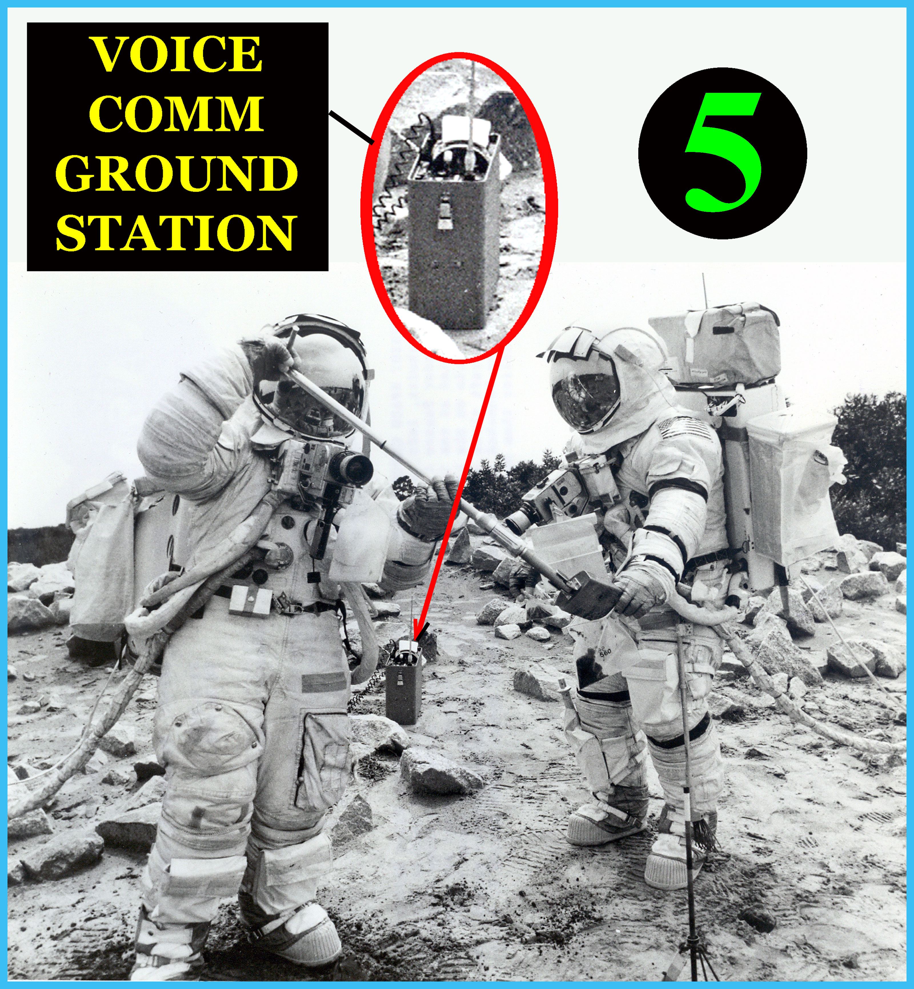
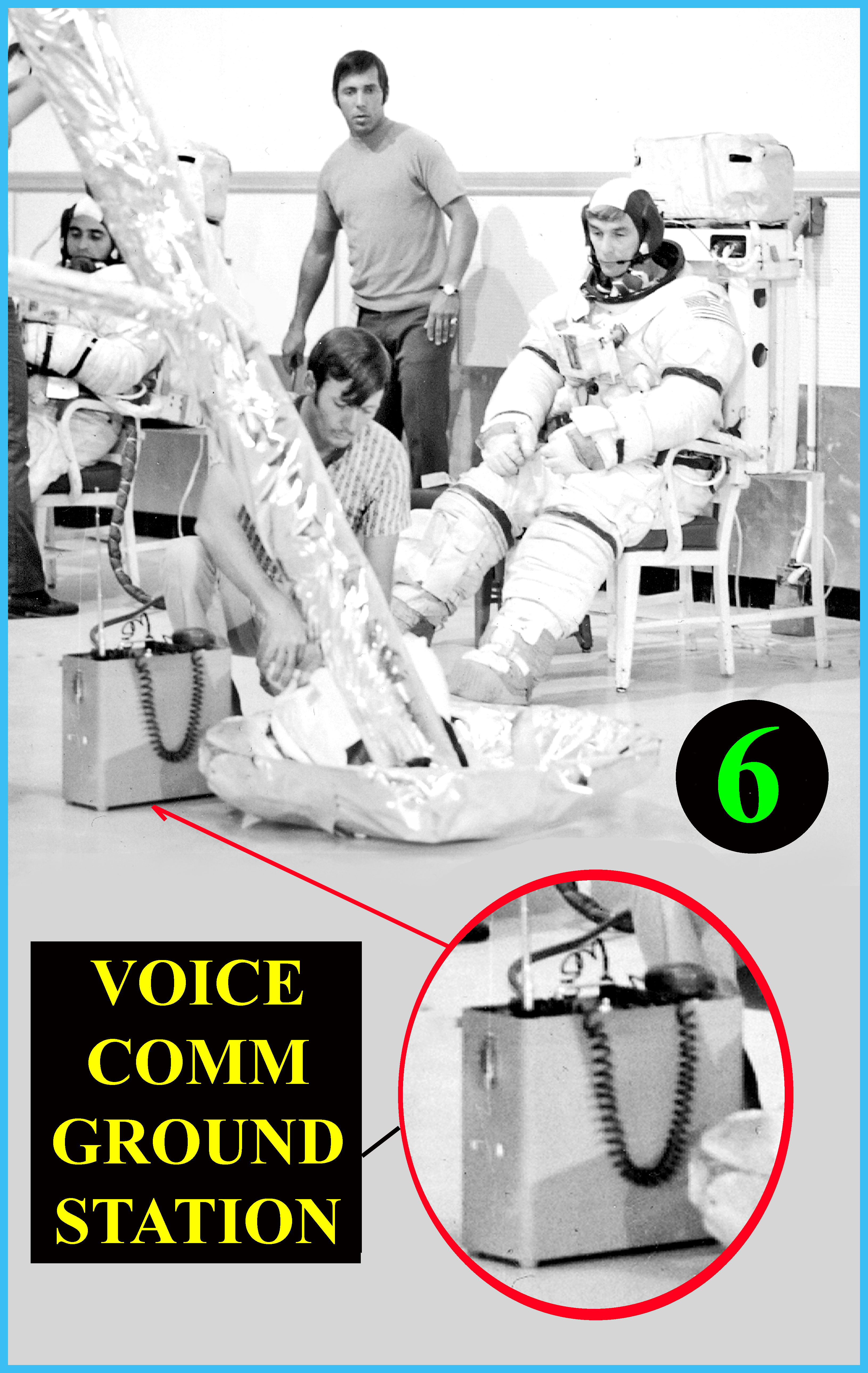
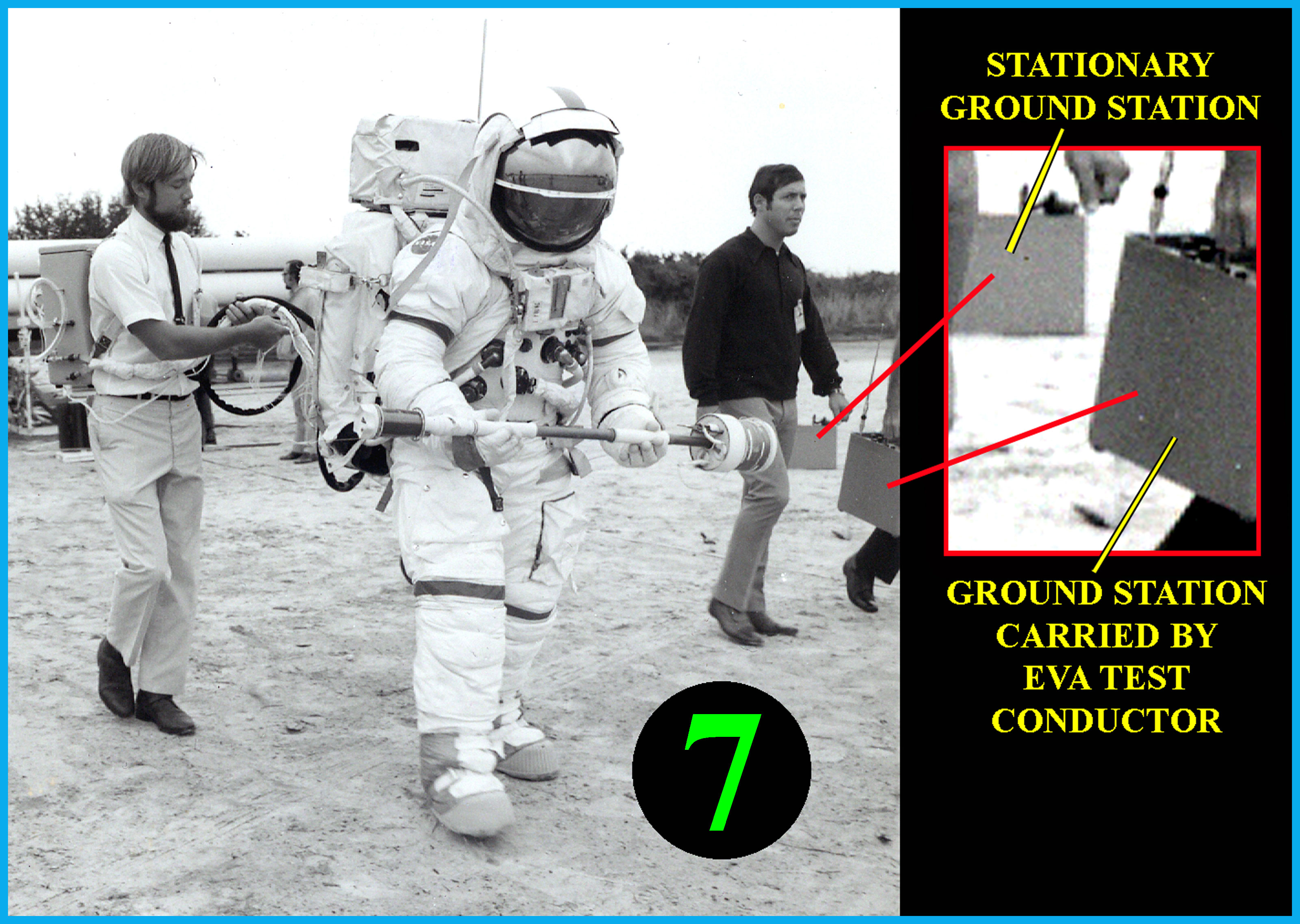
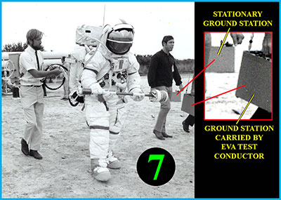
Continuing with the functional communications aspect of the EVA training Cryopack, the LM (not literally) was "replaced" by a Ground Station capable of sending and receiving voice communications (Photos 5, 6 and7). The Ground station had a speaker and a microphone attached to an expandable cord. Speaker voice content could easily be heard within a 20 to 30 foot radius of the station. The Ground station was also portable so it could be carried from one training site to another (see photos 5, 6 and 7 below). For every crew training EVA exercise there were two ground stations, one used by the test conductor and the other used by techs and myself.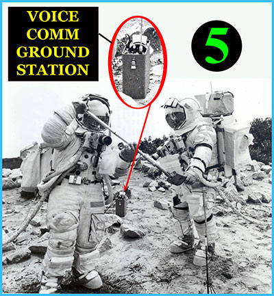 
|
Daniel on the Moon
Member Posts: 354
From: Bronxville, NY
Registered: Jun 2015
|
posted 11-14-2016 10:55 PM
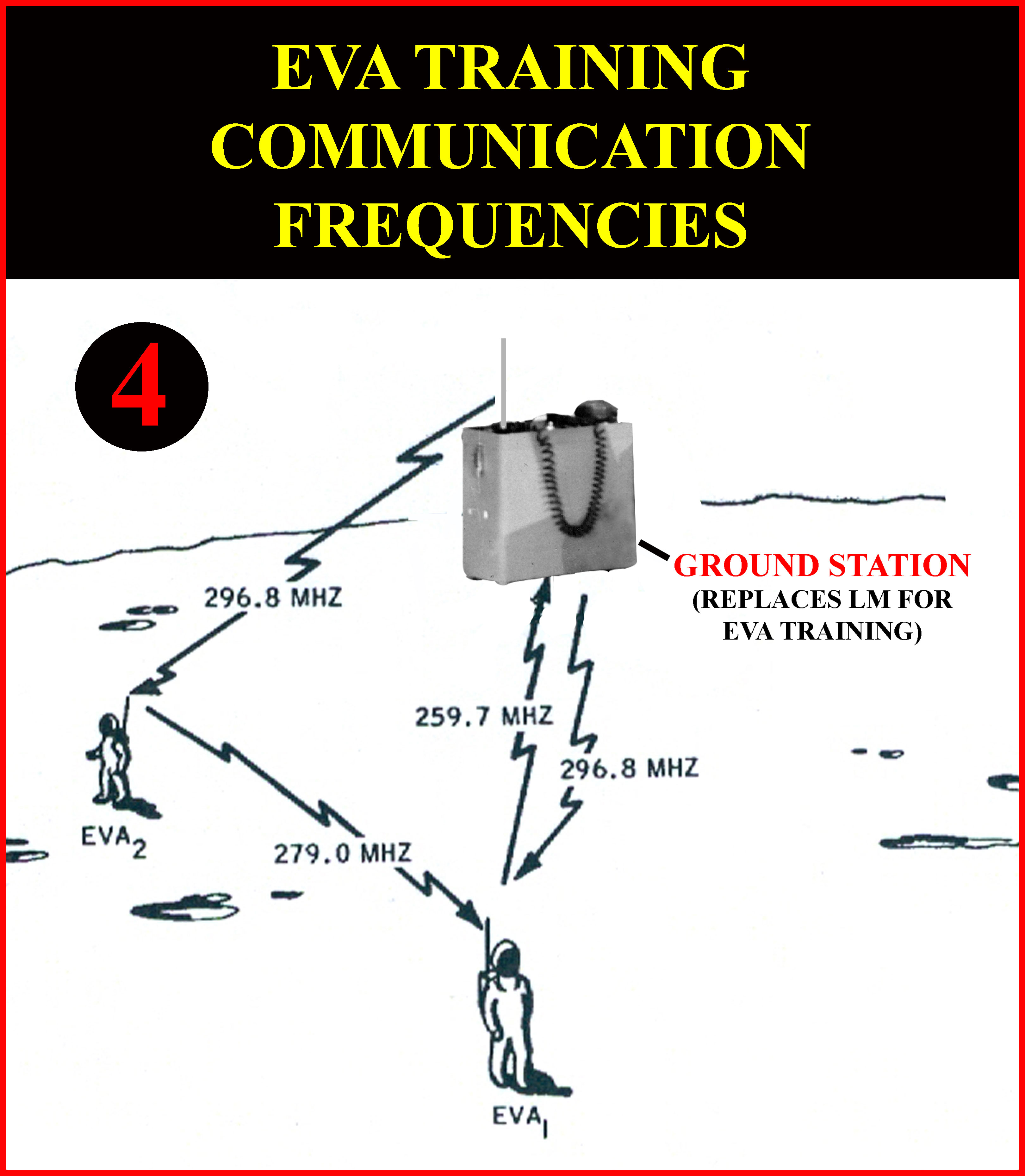
Completing the Cryopack communications description, it should be pointed out that Communication frequencies were identical to the frequencies used between the crew and the LM on the Lunar surface, i.e. 296.8 MHZ,279.0 MHZ and 259.7 MHZ (Figure 4). One day before all scheduled EVA training exercises I had to call for frequency clearance to use the three required frequencies. |