|
Author
|
Topic: Saturn V S-IC engine start sequence
|
LM-12
Member Posts: 3764
From: Ontario, Canada
Registered: Oct 2010
|
 posted 01-17-2018 04:56 PM
  
It is interesting to note that during launch of the Saturn V, the startup sequence for the five F-1 engines of the S-IC first stage was not the same for each flight. From the AS-512 (Apollo 17) launch vehicle flight evaluation report: Structurally, a 1-2-2 start is desired for minimizing the start and liftoff dynamics caused by thrust buildup of the engines ...The planned 1-2-2 F-1 engine start sequence ( engines 5, 3-1, 4-2 ) was not achieved. Two engines are considered to start together if both thrust chamber pressures reach 100 psig within 100 milliseconds. By this definition, the starting order was 2-1-1-1 ( engines 5-3, 1, 4, 2 ) ... The desired 1-2-2 start sequence was also not achieved on flights AS-507, AS-508 and AS-510. Here is a list of the sequences based on information in the flight evaluation reports: | flight | engine start
sequence | engine position
starting order | | AS-501 | 1-2-2 | 5, 3-1, 4-2 | | AS-502 | 1-2-2 | 5, 1-3, 2-4 | | AS-503 | 1-2-2 | 5, 3-1, 2-4 | | AS-504 | 1-2-2 | 5, 3-1, 2-4 | | AS-505 | 1-2-2 | 5, 3-1, 2-4 | | AS-506 | 1-2-2 | 5, 1-3, 4-2 | | AS-507 | 1-2-1-1 | 5, 1-3, 2, 4 | | AS-508 | 1-2-1-1 | 5, 1-3, 2, 4 | | AS-509 | 1-2-2 | 5, 1-3, 2-4 | | AS-510 | 1-1-2-1 | 5, 3, 2-4, 1 | | AS-511 | 1-2-2 | 5, 3-1, 4-2 | | AS-512 | 2-1-1-1 | 5-3, 1, 4, 2 | | AS-513 | 1-1-1-1-1 | 5, 3, 1, 2, 4 |
|
LM-12
Member Posts: 3764
From: Ontario, Canada
Registered: Oct 2010
|
posted 01-18-2018 08:11 AM
The command module main display console has five F-1 engine indicator lights on Panel 1. From the CSM Displays & Controls document: LV RATE light glows red if launch vehicle angular rates are excessive, which can automatically initiate abort; LV GUID light glows red to indicate failure in launch vehicle guidance system, which can result in abort; SII SEP light glows white when staging is initiated and goes out when interstage skirt drops away from S-II after ignition; LV
ENGINES lights (arranged in same pattern as on vehicle - 1, 2, 3, and 4 are outboard and 5 is inboard) glow yellow before ignition
and go out when an engine reaches 90 percent of thrust; No. 1 light also operated for third-stage engine; two lights glowing (two engines below 90 percent thrust) can initiate automatic abort during first-stage burning. |
LM-12
Member Posts: 3764
From: Ontario, Canada
Registered: Oct 2010
|
posted 01-21-2018 12:43 PM
In this view of SA-500F at Pad 39A, the engine 1 position is at Fin A, the engine 2 position is at Fin B, the engine 3 position is at Fin C, and the engine 4 position is at Fin D (hidden). The engine 5 position is inboard. |
Blackarrow
Member Posts: 3572
From: Belfast, United Kingdom
Registered: Feb 2002
|
posted 01-21-2018 02:55 PM
In the photograph, is that a man leaning against a ladder below and slightly to the left of the letter "C" ? If so, he provides some sense of scale. |
SpaceAholic
Member Posts: 5235
From: Sierra Vista, Arizona
Registered: Nov 1999
|
posted 01-21-2018 02:55 PM

quote:
Originally posted by LM-12:
The command module main display console has five F-1 engine indicator lights on Panel 1.
Example (though this one configured for CM stacked on a Saturn IB):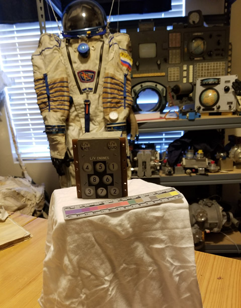 |
LM-12
Member Posts: 3764
From: Ontario, Canada
Registered: Oct 2010
|
posted 01-21-2018 03:16 PM
quote:
Originally posted by Blackarrow:
is that a man leaning against a ladder
Yes, I believe it is. Here is another view of SA-500F. Also, note that the B and C fin tips look damaged. |
LM-12
Member Posts: 3764
From: Ontario, Canada
Registered: Oct 2010
|
posted 01-21-2018 08:13 PM
During the second stage S-II propulsion phase of the Apollo 13 launch, the center engine (number 5) cut off about two minutes earlier than planned. How was that early engine cut off seen by the crew on their LV ENGINES indicator?That scene in the Apollo 13 movie shows the CM display console with the engines 1-4 lights illuminated and the center engine 5 light flashing on and off. Is that how the Apollo 13 crew saw their lights?
|
SpaceAholic
Member Posts: 5235
From: Sierra Vista, Arizona
Registered: Nov 1999
|
posted 01-21-2018 08:51 PM
Indicators 1-4 should be extinguished and 5 returned to "Yellow." |
LM-12
Member Posts: 3764
From: Ontario, Canada
Registered: Oct 2010
|
posted 01-22-2018 10:56 AM
From the AS-506 (Apollo 11) launch vehicle flight evaluation report: Engine startup sequence was nominal. A 1-2-2 start was planned and attained. Engine position starting order was 5, 1-3, 4-2. The graph in Figure 5-2 on page 5-3 seems to show that engine 3 started slightly before engine 1, which would make the engine position starting order 5, 3-1, 4-2. |
oly
Member Posts: 1443
From: Perth, Western Australia
Registered: Apr 2015
|
posted 01-22-2018 08:46 PM
quote:
Originally posted by LM-12:
...Figure 5-2 on page 5-3 seems to show that engine 3 started slightly before engine 1, which would make the engine position starting order 5, 3-1, 4-2.
The detail on this graph is not fine enough to make that call. There was a ignition sequence start trigger that puts the start sequence into action that seems to show engine 5 engine buildup transients begin to register at about T-3.4 seconds, engine 1 and 3 begin to register just prior to T-3 seconds and engines 2 and 4 begin to register at about T-2.75 seconds however there is not enough resolution to determine the sequence of engine ignition between the paired engines. What is shown is how impressive 50 year old technology was to sequence 5 huge rocket engines to ignite and accelerate to full thrust so accurately using automation considering all the steps, weight and quantity of fluids and gasses involved. |
LM-12
Member Posts: 3764
From: Ontario, Canada
Registered: Oct 2010
|
posted 01-24-2018 11:22 AM
The "S-IC Stage Engine Startup Event Times" for Apollo 8 are shown in Table 5-1 in the AS-503 launch vehicle flight evaluation report. I did not see a similar table in the AS-506 report for Apollo 11, unfortunately. |
mikej
Member Posts: 483
From: Germantown, WI USA
Registered: Jan 2004
|
posted 01-24-2018 05:42 PM
quote:
Originally posted by SpaceAholic:
Indicators 1-4 should be extinguished and 5 returned to "Yellow."
I have some information on both the Saturn IB and Saturn V version of the LV ENGINES subpanel on my website. |
LM-12
Member Posts: 3764
From: Ontario, Canada
Registered: Oct 2010
|
posted 01-24-2018 09:36 PM
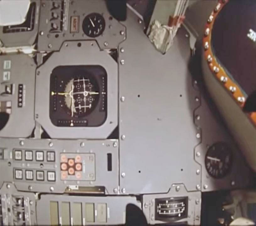
Apparently, the Apollo 6 command module also flew with the Saturn IB type LV ENGINES display. It can be seen in this 16mm onboard film of the control panel. |
LM-12
Member Posts: 3764
From: Ontario, Canada
Registered: Oct 2010
|
posted 01-25-2018 07:42 AM
Or is that AS-202 footage and not Apollo 6?
|
mikej
Member Posts: 483
From: Germantown, WI USA
Registered: Jan 2004
|
posted 01-25-2018 06:40 PM
While I cannot comment on the accuracy of the film's metadata, I seem to recall looking up Apollo 6's control panel when I did my Apollo 4 page and finding that it, too, had the Saturn IB LV ENGINES subpanel. (I couldn't immediately locate the document to which I referred at the time.)I also took a look the full-res version of a photo I took of Apollo 6's control panel at Fernbank Science Center and confirmed that it has the Saturn IB indicator. |
LM-12
Member Posts: 3764
From: Ontario, Canada
Registered: Oct 2010
|
posted 01-25-2018 10:50 PM
Some camera information from the press kits:From the AS-202 Press Kit: Four 16mm Milliken motion picture cameras will be mounted in the Command Module to record instruments, chute deployment and reentry. One camera will be mounted on the flat plate in the egress hatch (in the nose of the CM) to record jettisoning of the Apex cover, parachute deployment and reentry. The second camera is on a pallet where the right astronaut couch would be located, and will record liftoff and reentry through the right-hand window. Two instrument cameras, one on the left and one on the center, will record instruments and displays during the flight. From the Apollo 6 Press Kit: Two cameras will be mounted within the command module crew compartment. A 16mm Millikan motion picture camera will be pointed out the left rendezvous window. A 70mm Maurer still camera will photograph through the hatch window. |
LM-12
Member Posts: 3764
From: Ontario, Canada
Registered: Oct 2010
|
posted 01-26-2018 10:56 AM
The Saturn-IB launch vehicle flight evaluation reports mention that the automatic ignition sequence scheduled the eight H-1 first-stage engines to start in pairs, with a 100 millisecond delay between each pair. The engine pairs were 5-7, 6-8, 2-4 and 1-3. |
LM-12
Member Posts: 3764
From: Ontario, Canada
Registered: Oct 2010
|
posted 12-14-2018 08:14 PM
Some of the Apollo 16 CM control panels (including Panel 1 on the main console) were reused and installed in the ASTP command module. The LV ENGINES indicator located on Panel 1 was replaced with a Saturn IB version. It can be seen in photo AST-008-499. The Saturn IB indicator is not on the CSM-111 reused flight hardware list. Any idea where the flown Apollo 16 LV ENGINES indicator ended up? |
LM-12
Member Posts: 3764
From: Ontario, Canada
Registered: Oct 2010
|
posted 04-05-2023 12:04 AM
This NASA article posted yesterday about the 55th anniversary of Apollo 6 has a photo of the LV ENGINES indicator lit up in-flight. As mentioned earlier, the Apollo 6 Saturn V had a Saturn IB type LV ENGINES indicator.Still image from a film taken by an onboard camera showing the Apollo 6 Command Module (CM) control panel during the mission. 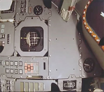 |