|
Author
|
Topic: Apollo crews in lunar module on launch pad
|
oly
Member Posts: 1484
From: Perth, Western Australia
Registered: Apr 2015
|
 posted 02-01-2016 08:40 AM
   
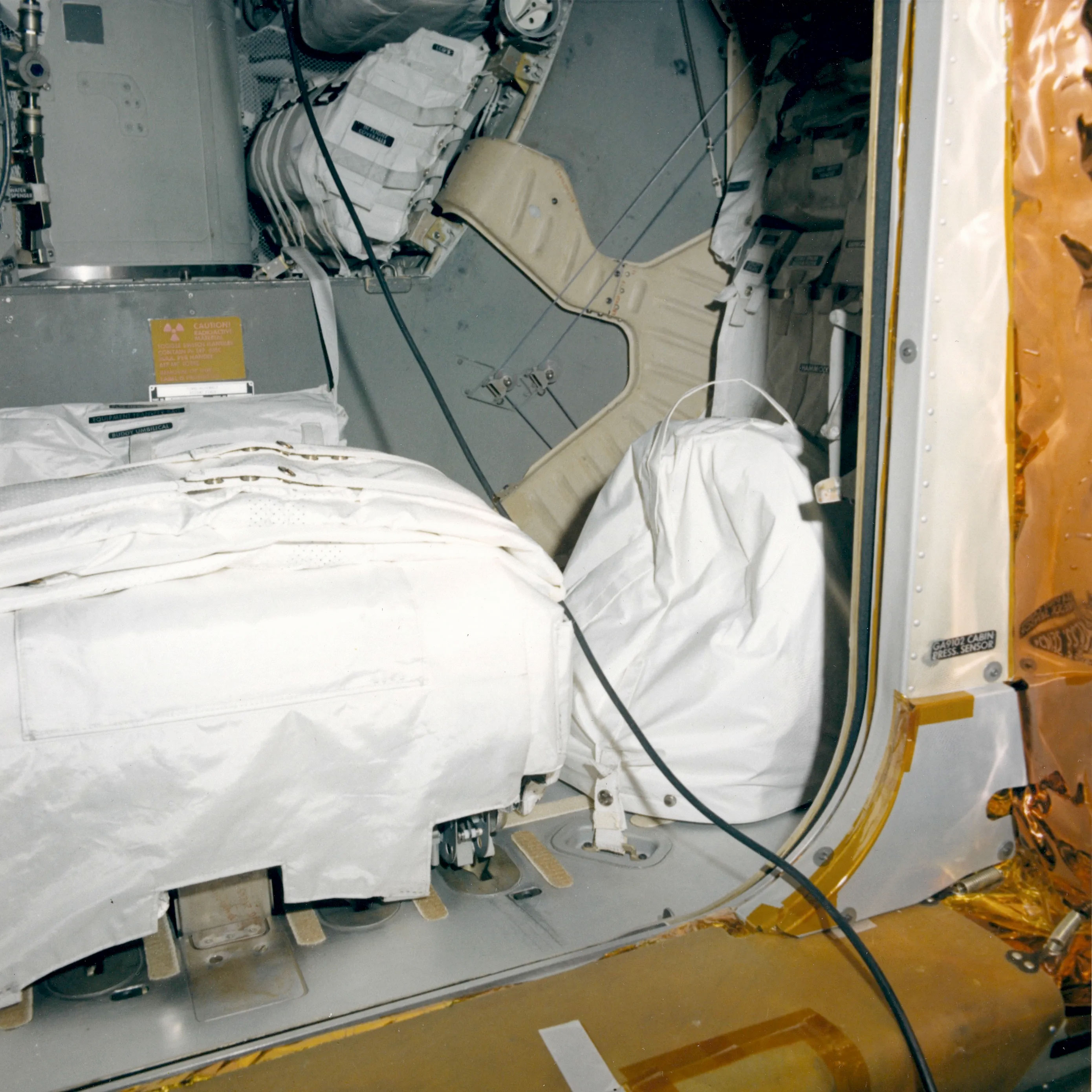
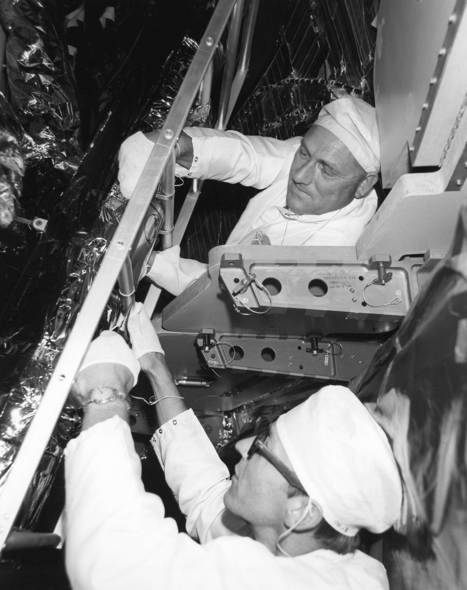
Looking at the Apollo Lunar Surface Journal website at the pre-launch LM close out photo pages there are some photos that show the LM porch and lower section of the hatch opening. Here you can see some of the gantry floor segments that allow access to the LM. This may help identify the access available. While I was browsing I found these photos. What I found to be curious is where is the hatch and how could it be closed pre-launch with all these items stowed on the LM floor? Any thoughts? 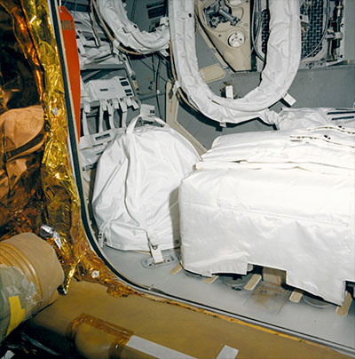 
|
LM-12
Member Posts: 4009
From: Ontario, Canada
Registered: Oct 2010
|
posted 02-01-2016 04:15 PM
The Apollo 10 schedule has the "LM4 Mission Simulation (FRT)" on April 8 with Stafford and Mitchell, and the "LM CCFF" on April 10 with Stafford and Cernan. |
Daniel on the Moon
Member Posts: 354
From: Bronxville, NY
Registered: Jun 2015
|
posted 02-01-2016 06:43 PM
quote:
Originally posted by oly:
What I found to be curious is where is the hatch and how could it be closed pre-launch with all these items stowed on the LM floor?
The hatch door is removed before LM stowage and replaced after stowage is complete. The hatch door hinges are on the inner left vertical side (looking through the hatch from outside) and the hatch opens to the inside. |
LM-12
Member Posts: 4009
From: Ontario, Canada
Registered: Oct 2010
|
posted 02-01-2016 09:22 PM
Inside the SLA, how much of a gap was there between the bottom of the SPS engine nozzle and the top of the LM ascent stage? |
CMikeW
Member Posts: 89
From: United States
Registered: Apr 2013
|
posted 02-01-2016 09:46 PM
This is going way back, but I believe the amount of clearance in the static position on the pad was in the order of six inches or less. I know that some clearance was needed to be sure the SPS nozzle didn't contact the LM during the boost phase of flight. The stack seems pretty rigid but the structure would grow and bend from dawn to sundown because of solar heating. |
LM-12
Member Posts: 4009
From: Ontario, Canada
Registered: Oct 2010
|
posted 02-02-2016 01:05 AM
Pretty amazing how all that came together. |
oly
Member Posts: 1484
From: Perth, Western Australia
Registered: Apr 2015
|
posted 02-02-2016 09:32 AM
I have noticed in this photo that the lower hatch hinge appears to be a type of parrot beak style mechanism. Is anyone aware if this is the case and if so how is it actuated to engage the hatch during installation? 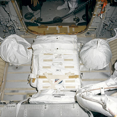 I may be on the wrong track here. It seems to be a tight fit to install the hatch from outside. Is anyone aware of the procedures for this? Also, with the view of the floor outside the LM on the previous close out photos, was this the same possible access astronauts had to the LM and how long before launch were the close out photos taken? |
LM-12
Member Posts: 4009
From: Ontario, Canada
Registered: Oct 2010
|
posted 02-03-2016 09:02 PM
This Apollo 15 photo 71-HC-932 must have been taken in the MSS. On a higher platform, of course.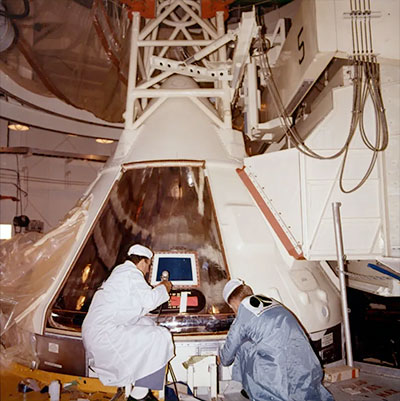 |
bunnkwio
Member Posts: 114
From: Naperville, IL USA
Registered: Jul 2008
|
posted 02-09-2016 12:36 PM
quote:
Originally posted by oly:
I have noticed in this photo that the lower hatch hinge appears to be a type of parrot beak style mechanism.
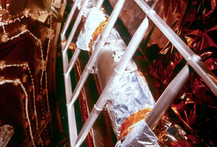
Dumb question... what is the use of the blue wire pulley mechanism attached to the walls on each side of the hatch? |
CMikeW
Member Posts: 89
From: United States
Registered: Apr 2013
|
posted 02-09-2016 03:17 PM
quote:
Originally posted by LM-12:
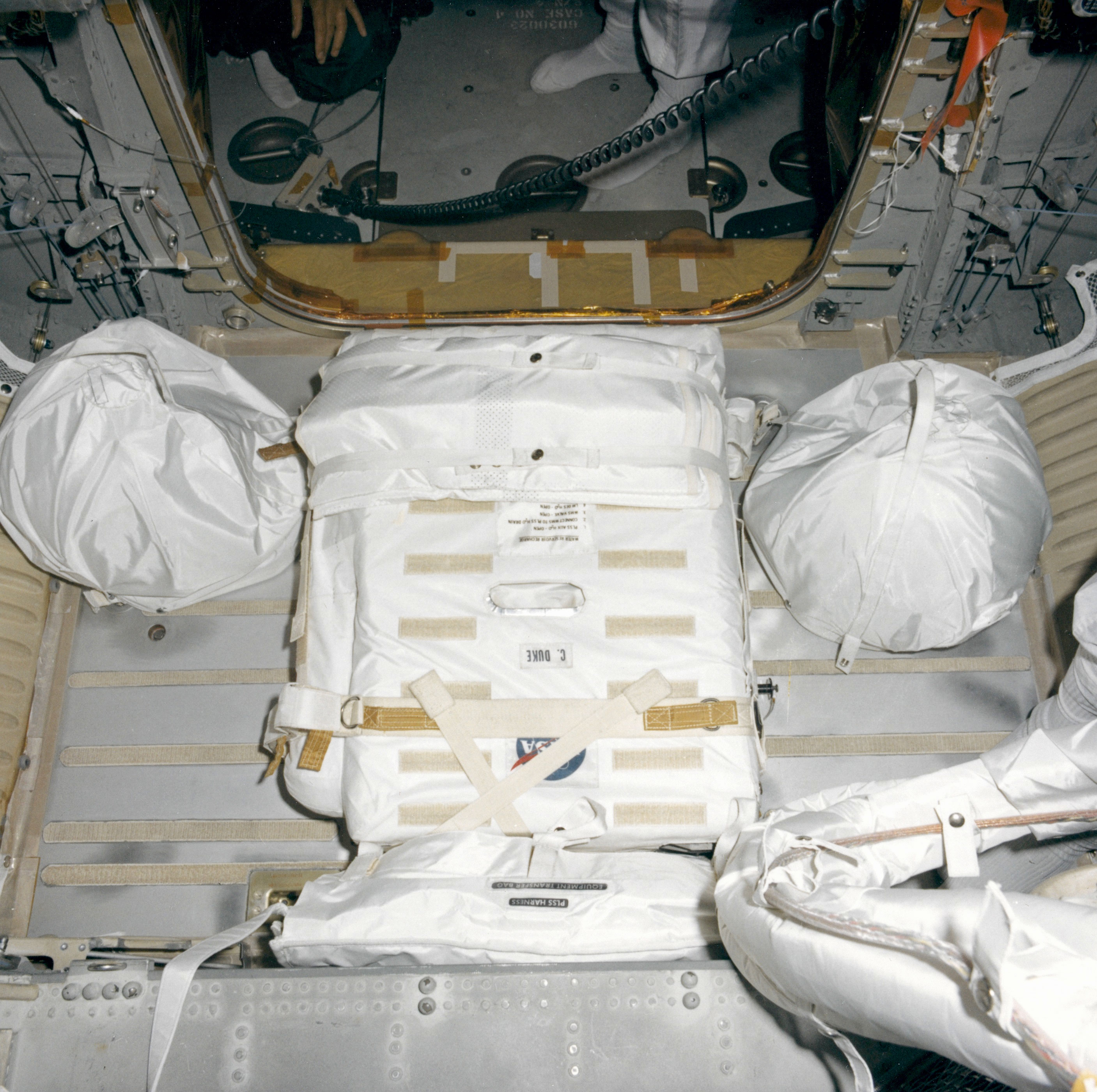
Looking at this transposition and docking photo, I can only imagine how cramped it must have been working inside the SLA on the pad.
I remember that we, NAA, installed padding on the inside of the SLA to minimize damage to the thin Al face sheet of the SLA that was exposed during Grumman activities at the pad. The techs called the padding "Ginnie Bumpers." The padding consisted of two layers of foam padding about a 1/4 inch thick with a thin sheet of SS or AL between them. |
LM-12
Member Posts: 4009
From: Ontario, Canada
Registered: Oct 2010
|
posted 02-09-2016 04:21 PM
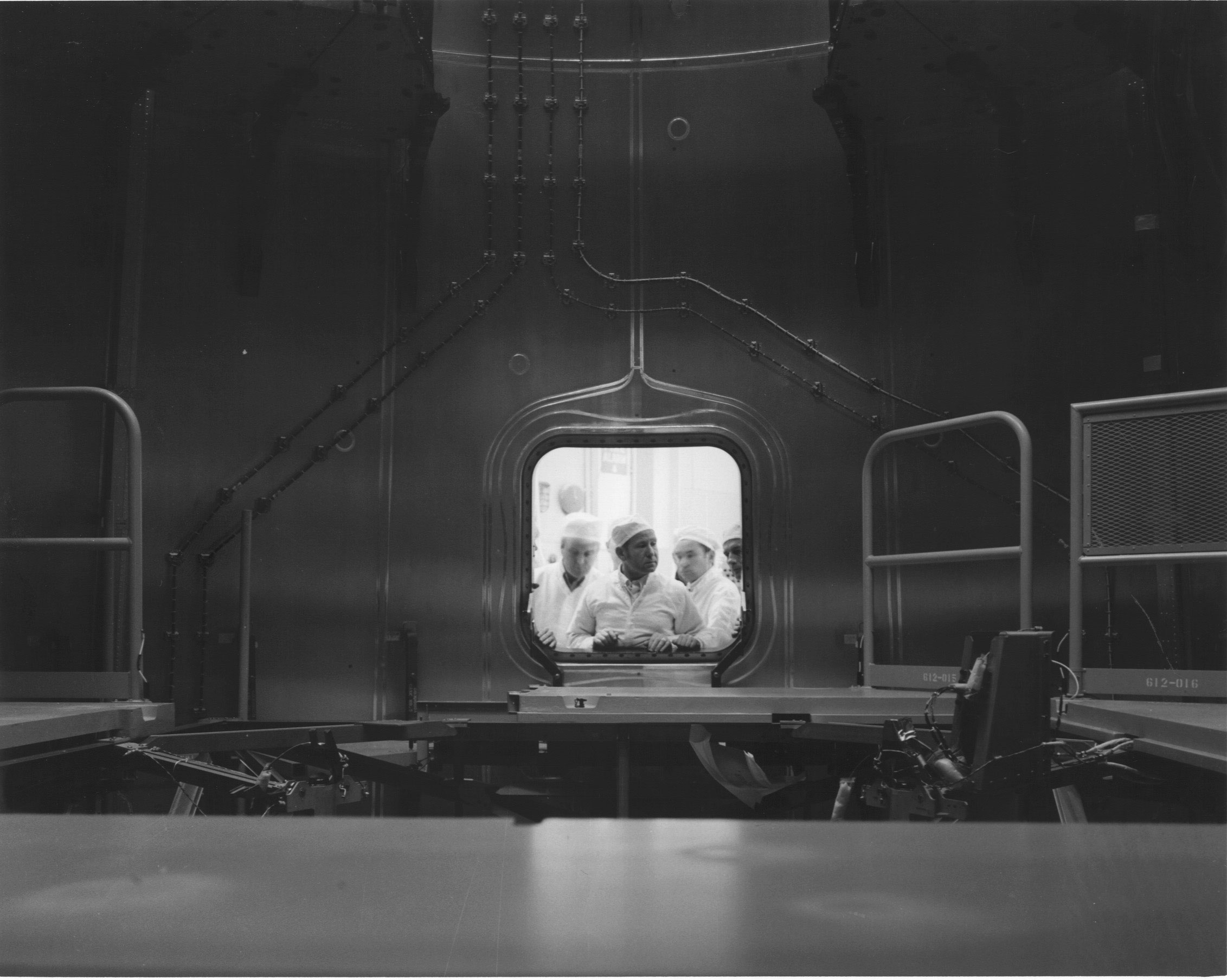
This 1975 ASTP photo shows an interior view of the SLA with some work platforms visible and cosmonaut Alexei Leonov at one of the access doors. |
Jim Behling
Member Posts: 1948
From: Cape Canaveral, FL
Registered: Mar 2010
|
posted 02-09-2016 06:56 PM
quote:
Originally posted by bunnkwio:
What is the use of the blue wire pulley mechanism attached to the walls on each side of the hatch?
The astronaut restraint system. |
CMikeW
Member Posts: 89
From: United States
Registered: Apr 2013
|
posted 02-09-2016 07:00 PM
The access situation in the SLA for the ASTP program was quite different since the Docking Module used to perform the adaption between the Russian Docking system and the US docking system sat on an aluminum truss structure that was attached to the LEM/LM attach points on the SLA. Lots more room to move around. As I remember it there was very little clearance between the LEM and the sides of the SLA in most areas. |
LM-12
Member Posts: 4009
From: Ontario, Canada
Registered: Oct 2010
|
posted 02-09-2016 07:50 PM
Which of the Apollo missions did you personally work on at Pad 39? |
CMikeW
Member Posts: 89
From: United States
Registered: Apr 2013
|
posted 02-09-2016 09:12 PM
Minor involvement on Apollo 10 and 11. Much more on 12 through the end of the program. |
LM-12
Member Posts: 4009
From: Ontario, Canada
Registered: Oct 2010
|
posted 02-09-2016 09:52 PM
To have been working at that place at that time -- how interesting! |
Ken Havekotte
Member Posts: 3881
From: Merritt Island, Florida, Brevard
Registered: Mar 2001
|
posted 02-10-2016 04:34 AM
For "CMikeW," Is this the same Michael W. that I knew from Titusville, FL, and in association with the T-MSC? This is Ken H. of Merritt Island and I do have some photos of you--if we're talking about the same person--atop Pad 39 inside the MSS during the Apollo era. |
LM-12
Member Posts: 4009
From: Ontario, Canada
Registered: Oct 2010
|
posted 02-10-2016 02:37 PM
Figure 5.43 in Jonathan Ward's Countdown to a Moon Launch has a diagram of the work platforms installed around the LM in the upper SLA section. Other work platforms in the lower SLA section were in place before the LM was lowered into the SLA. |
mikej
Member Posts: 483
From: Germantown, WI USA
Registered: Jan 2004
|
posted 02-10-2016 05:48 PM
quote:
Originally posted by bunnkwio:
what is the use of the blue wire pulley mechanism attached to the walls on each side of the hatch?
To expand on Jim's answer, a bit more on the astronaut restraint system. |
bunnkwio
Member Posts: 114
From: Naperville, IL USA
Registered: Jul 2008
|
posted 02-10-2016 10:20 PM
Thank you both!! I always knew of the foot restraints, but never read up on this restraint system! |
Space Cadet Carl
Member Posts: 305
From: Lake Orion, MI
Registered: Feb 2006
|
posted 02-11-2016 06:26 AM
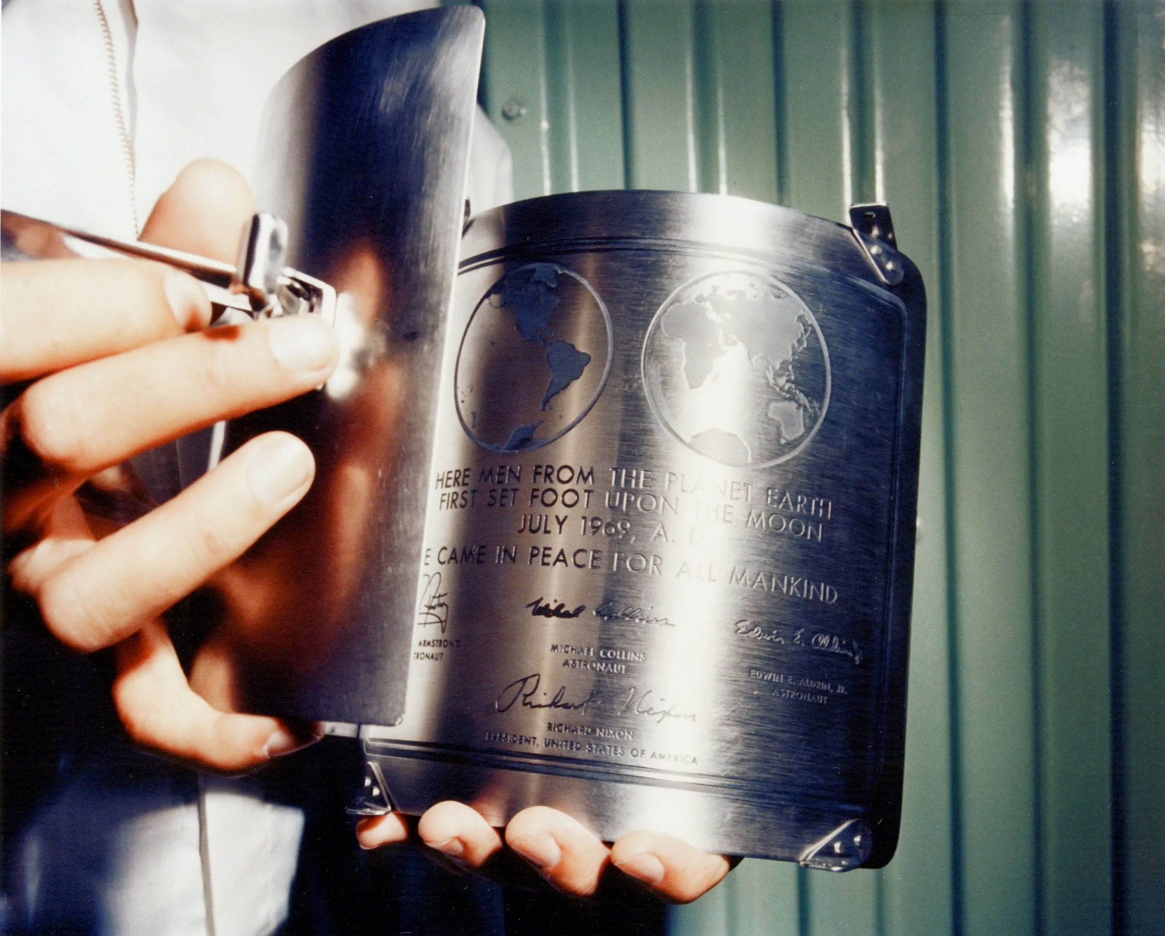
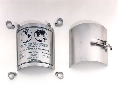
Most of us had no idea how much work took place inside the SLA on the pad. I knew about the commemorative plaque and American flag, but apparently that was just a tiny percentage of the work done inside there. Thanks to everyone for this great discussion. |
LM-12
Member Posts: 4009
From: Ontario, Canada
Registered: Oct 2010
|
posted 02-11-2016 06:40 AM
That is just about what I thought also. I certainly had no idea that the LM crews were in there on the pad. |
LM-12
Member Posts: 4009
From: Ontario, Canada
Registered: Oct 2010
|
posted 02-12-2016 12:22 AM
This LM-10 closeout photo taken at Pad 39A shows a view out the forward hatch where you can see a work platform between the hatch opening and the aluminum skin of the SLA. |
Jim Behling
Member Posts: 1948
From: Cape Canaveral, FL
Registered: Mar 2010
|
posted 02-12-2016 06:39 AM
It also shows the duct that supplies fresh air for the workers.
|
LM-12
Member Posts: 4009
From: Ontario, Canada
Registered: Oct 2010
|
posted 02-12-2016 08:40 AM
The caption for photo KSC-72P-114 indicates that the Apollo 16 LM plaque was attached inside the SLA at the pad six days before launch. Note the comments by author Jonathan Ward.An uplock assembly can be seen behind the ladder leg. From the Lunar Module News Reference: One uplock assembly is attached to each landing gear assembly. It consists of a fixed link (strap) and two end detonator cartridges in a single case. The fixed link, attached between the primary strut and the descent stage structure, holds the landing gear in its retracted position. When the Commander operates the landing gear deployment switch, it activates an electrical circuit which explosively severs the fixed link to permit the deployment mechanism to extend the landing gear. When detonated, either end cartridge has sufficient energy to sever the fixed link.  |
LM-12
Member Posts: 4009
From: Ontario, Canada
Registered: Oct 2010
|
posted 02-13-2016 05:51 AM
quote:
Originally posted by moonguyron:
LM Closeout-Installed the flag carrier and the plaque.
The NASA Where No Flag Has Gone Before document says that "the flag and plaque were installed on the LM of Apollo 11 at 4:00 in the morning as the spacecraft sat atop its Saturn V rocket ready for launch." Was that 4:00 in the morning on launch day or the 15th?
|
LM-12
Member Posts: 4009
From: Ontario, Canada
Registered: Oct 2010
|
posted 02-14-2016 10:27 AM
This Apollo 11 photo of LM-5 is dated April 4, which I believe is the day the LM was installed in the SLA. Notice the LM still has a landing gear probe on the +Z footpad. The CSM was mated to the SLA on April 11. The Apollo spacecraft was moved to the VAB on April 14.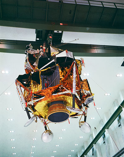 Not sure how much work was done inside the SLA in the VAB. On later missions, the rollout took place less than a week after the Apollo spacecraft was stacked on the launch vehicle. Photo of the Week 252 was taken in the LM in the VAB. |
oly
Member Posts: 1484
From: Perth, Western Australia
Registered: Apr 2015
|
posted 02-15-2016 08:30 AM
These photos show the Apollo 11 plaque in various pre and post installation shots:  

|
LM-12
Member Posts: 4009
From: Ontario, Canada
Registered: Oct 2010
|
posted 02-16-2016 10:01 AM
quote:
Originally posted by LM-12:
work platforms installed around the LM
Some of those work platforms at the hatch level can be seen in this KSC-71C-803 photo looking up the Apollo 14 LM ladder in the SLA.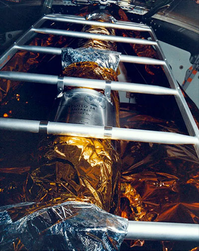 |
F1 Fumes
New Member Posts: 4
From: The Netherlands
Registered: Nov 2015
|
posted 02-16-2016 02:03 PM
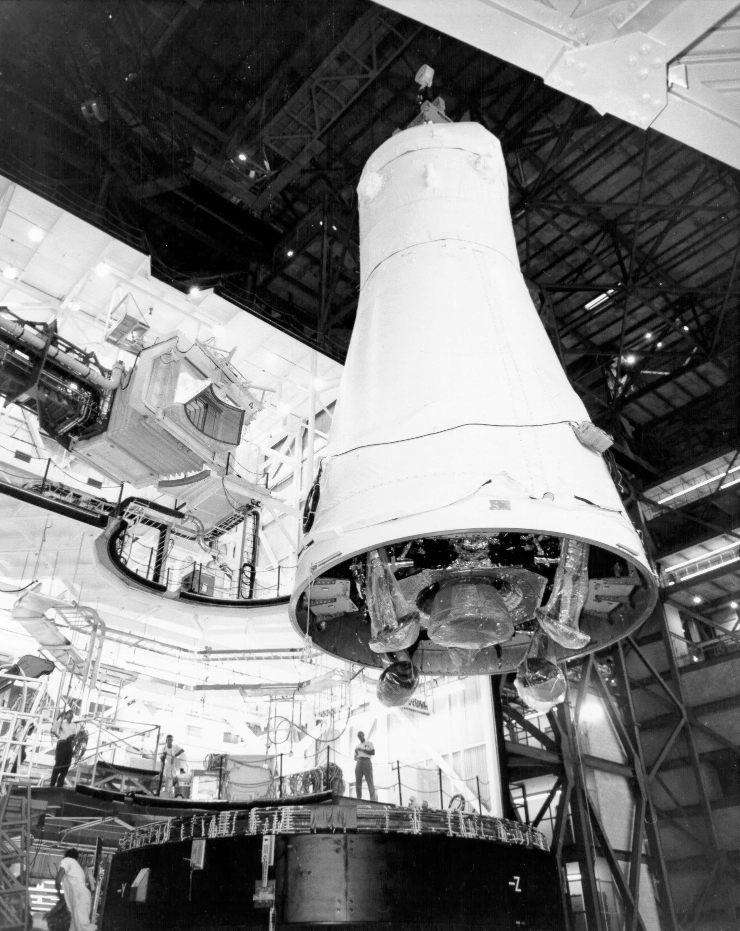
In this Apollo 12 stacking photo, some work platforms can be seen attached to the sides of the SLA. Presumably similar platforms were used for for access to the ascent stage.  |
LM-12
Member Posts: 4009
From: Ontario, Canada
Registered: Oct 2010
|
posted 02-16-2016 02:32 PM
It looks like the platforms seen inside the SLA in the Apollo 12 photo would have been the ones used to install the plaque at the pad. Also inside the SLA: the service module S-Band high-gain antenna in its stowed position next to the SPS engine nozzle. There was a work platform in the SLA to reach that level. |
oly
Member Posts: 1484
From: Perth, Western Australia
Registered: Apr 2015
|
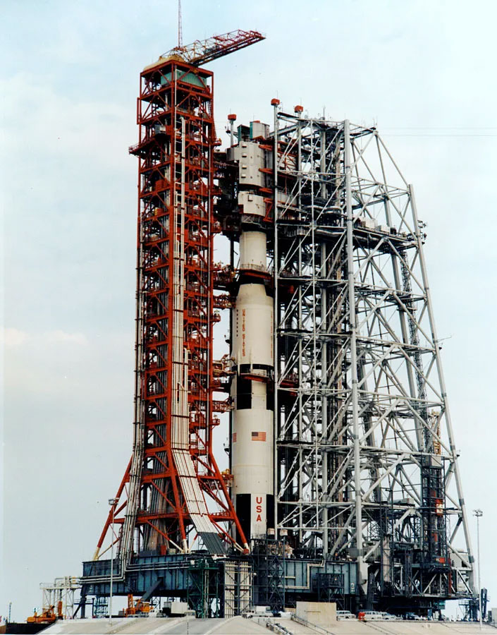
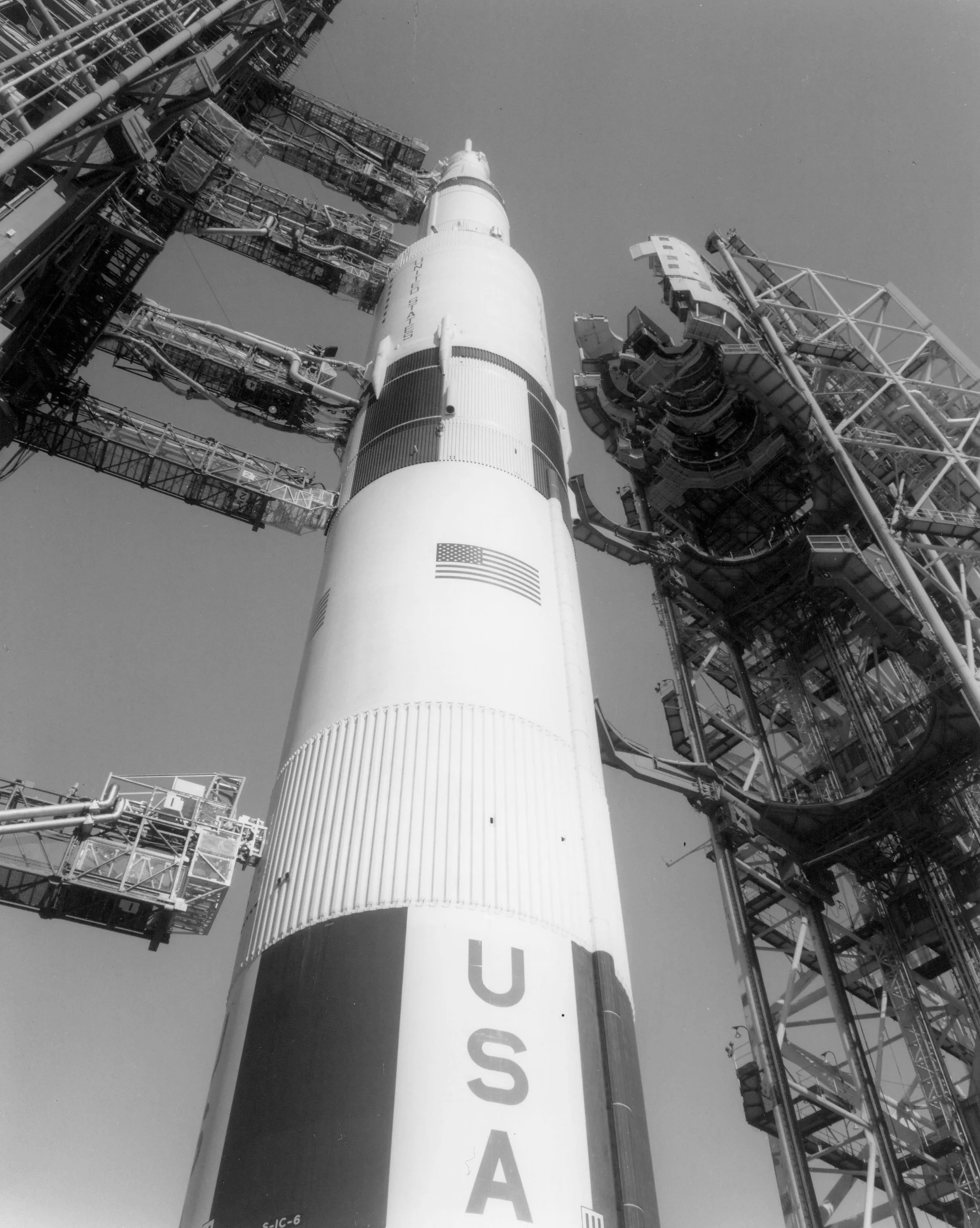
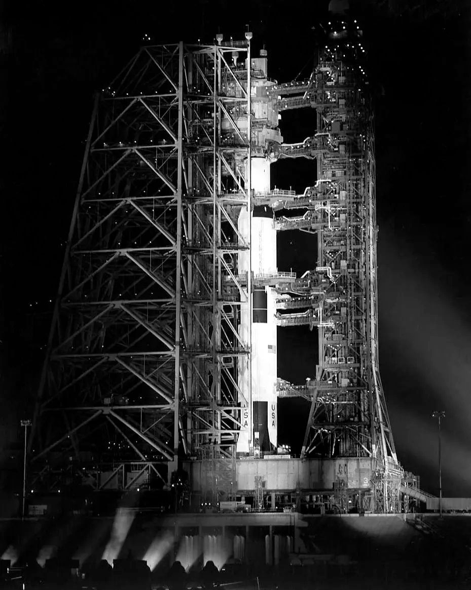
posted 02-17-2016 02:35 AM
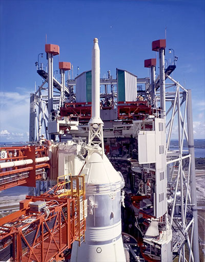
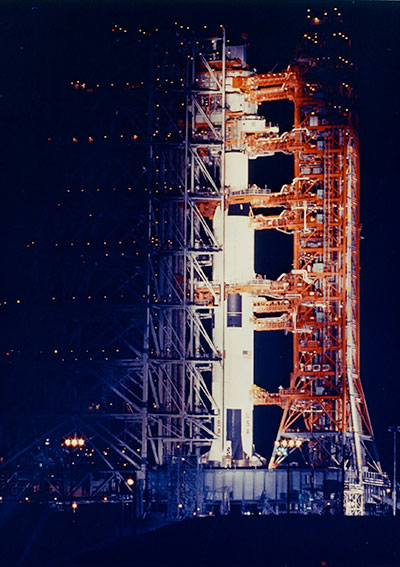
These photos show some details of the Saturn V and Apollo via the LUT and MSS access on the pad.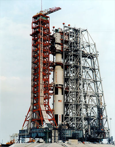 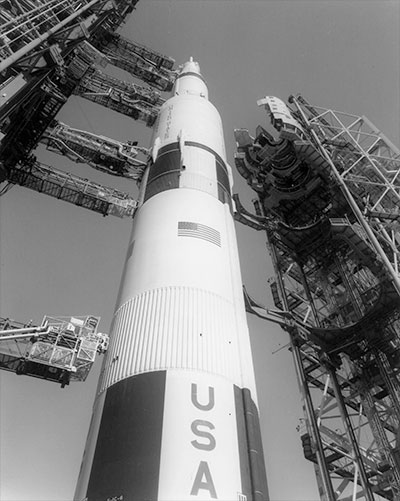

|
Jim Behling
Member Posts: 1948
From: Cape Canaveral, FL
Registered: Mar 2010
|
posted 02-17-2016 04:45 AM
It is funny, but the configurations we are the most familiar with are the Saturn V and Shuttle at the pad just before launch. When in reality, those were the least "common" configuration, since the Saturn V and Shuttle enclosed by the MSS/RSS most of the time. It actually applies to most launch vehicles. I was at the Cape in its most recent heyday, the 90's (two shuttle, two Titan, two Atlas and two Delta pads). There would be occasions where at least one of each vehicle type was at the pad (sometimes two). But, you would never really notice unless you looked directly at the pads and spied the vehicle through the service structure. Not the same for the Saturn V and clean pad concept. It was obvious, when a vehicle was at the pad. |
oly
Member Posts: 1484
From: Perth, Western Australia
Registered: Apr 2015
|
posted 02-17-2016 08:30 AM
Good point Jim. Most of us are more familiar with the images we see on TV from the countdown and launches. We are not tuned to seeing the assembly, erecting and testing procedures. |
LM-12
Member Posts: 4009
From: Ontario, Canada
Registered: Oct 2010
|
posted 02-17-2016 08:40 AM
The long rollout to Pad 39 with the vehicle visible like that sure was an impressive sight. |
Jim Behling
Member Posts: 1948
From: Cape Canaveral, FL
Registered: Mar 2010
|
posted 02-17-2016 08:47 AM
quote:
Originally posted by oly:
Good point Jim. Most of us are more familiar with the images we see on TV from the countdown and launches. We are not tuned to seeing the assembly, erecting and testing procedures.
Pictures of the MSS around the vehicle is an exception vs the rule and inverse of the time that it spent around the vehicle.
|
Jim Behling
Member Posts: 1948
From: Cape Canaveral, FL
Registered: Mar 2010
|
posted 02-17-2016 08:49 AM
quote:
Originally posted by LM-12:
The long rollout to Pad 39 with the vehicle visible like that sure was an impressive sight.
Back in the day, I would occasionally reroute my path into work to drive along the crawler way while the shuttle was going out to the pad.
|
LM-12
Member Posts: 4009
From: Ontario, Canada
Registered: Oct 2010
|
posted 02-17-2016 10:07 AM
When Apollo 16 rolled back to the VAB in January 1972 to repair a fuel system leak, there was no protective cover over the SLA. There was a cover over the CSM. Both had covers for rollout #2. |
LM-12
Member Posts: 4009
From: Ontario, Canada
Registered: Oct 2010
|
posted 02-23-2016 09:45 AM
The extra insulation and plume deflectors installed on the LM-5 descent stage at the pad are among the configuration differences between AS-505 and AS-506 mentioned in the mission report: - Modified the base heat shield. Reduces the lunar landing fire-to-touchdown problem. Enhances mission success.
- Added RCS plume deflectors for each of the lower four RCS thrusters. To withstand increased firing time for RCS thrusters.
In the post-flight debrief, Buzz Aldrin discusses the LM inspection done early in the EVA. He mentions the plume deflectors: I don't think we noticed a thing that was abnormal. I guess the only thing that I made note of was the jet plume deflectors. The one on the right side as I was looking at the LM (which would make it the quad 1) appeared to be a bit more wrinkled than the one on quad 4. Of course, there's nothing to compare it with, because I'd never seen them before. As a matter of fact, the first time we really saw them was when we looked out of the command module and got a pretty good idea of their structure. |
LM-12
Member Posts: 4009
From: Ontario, Canada
Registered: Oct 2010
|
posted 02-24-2016 10:21 PM
Found another date for Apollo 14 astronauts in the LM at the pad: - "LM CCFF" on Dec 16 ... Shepard-Mitchell (0800-1200)
- "LM CCFF" on Dec 16 ... Cernan-Engle (1200-1600)
|