|
Author
|
Topic: Ventilation system for Apollo A7L spacesuit
|
Apolloman
Member Posts: 225
From: Ledignan, Gard (30), France
Registered: Mar 2009
|
 posted 04-06-2024 08:32 AM
   
I still have a question (it's a pretty stubborn habit of mine) about one of the technologies used for the Apollo A7L pressure suit.First of all, the context: I have in front of me two PDF documents: - Apollo Operations handbook extra vehicular mobility unit Volume 1 system description CSD-A-789-(1) Apollo 14
- Ventilation system for inflatable pressure garments (United States Patent US3667460)
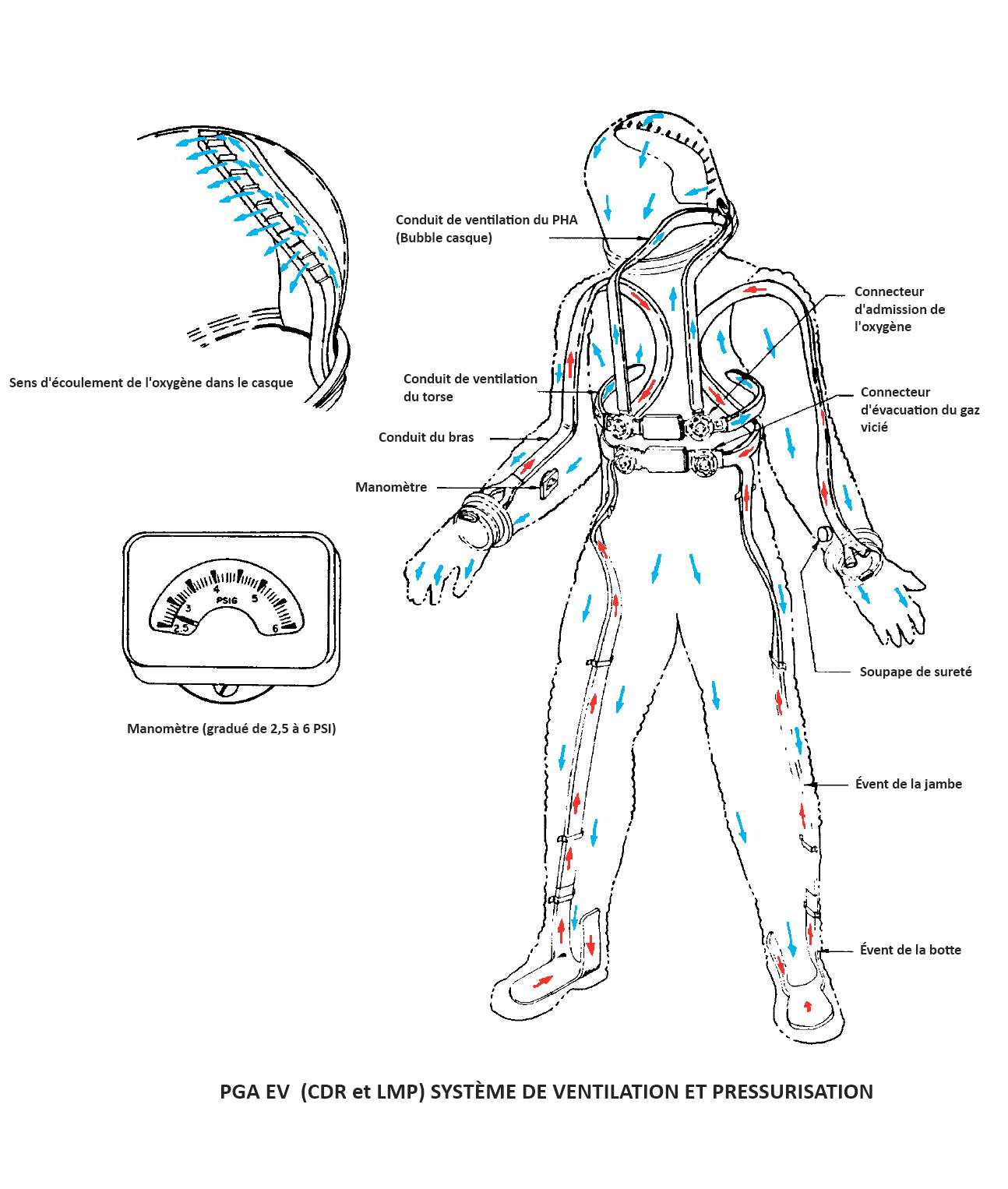
And if anyone would like a copy, I could send it to them (via email). If you read both documents, you end up with contradictory information. Pages 107 and 108 of the first document show diagrams of the IV pressurization/ventilation system (107) and the EV pressurization/ventilation system (108).If you look closely at the drawings, you'll see that the flow of contaminated (black arrow) gas goes up through the feet and arms to the outlet connectors via the appropriate channels. The second document states (and I quote): ...the life support gas enters at the helmet and through ducts at the extremities of the arms and exits from the garment only through ducts located at the legs after passing over the entire body of the wearer. Do you understand me when I say that I don't know where I stand? Does anyone have an answer? |
DG27
Member Posts: 262
From: USA
Registered: Nov 2010
|
posted 04-09-2024 02:30 AM
The Apollo Operations Handbook correctly describes the flow of gas in the suit. Oxygen is fed into the suit thru the blue connector and sent to the helmet and to the horizontal distribution duct at the waist. For EVA operations the valve on the inlet connector is rotated to block oxygen flow to the waist duct and directs all oxygen to the helmet. Suit exhaust gas is collected in the gloves and feet of the suit and routed to the red outlet connector on the suit. The diagram and description in the patent may be an earlier configuration but does not reflect what was used for the Apollo A6L and A7L suits. The configuration described in the patent requires a 4-port oxygen inlet connector plenum and the ones used for Apollo only had 3 plenum ports (one port for the cross-feed duct to the other connector, one port for the helmet duct, and one port for the valve-controlled waist duct). I have yet to find any mention of changes in the direction of gas flow in the suit arms during suit development. The initial concept as captured in the patent apparently evolved with a reversal in gas flow in the arms. If NASA directed that change as a result of analysis or testing, then it would not be in the patent as the change was not part of the ILC invention. Good work on your part in finding the differences. |
Apolloman
Member Posts: 225
From: Ledignan, Gard (30), France
Registered: Mar 2009
|
posted 04-13-2024 03:37 AM
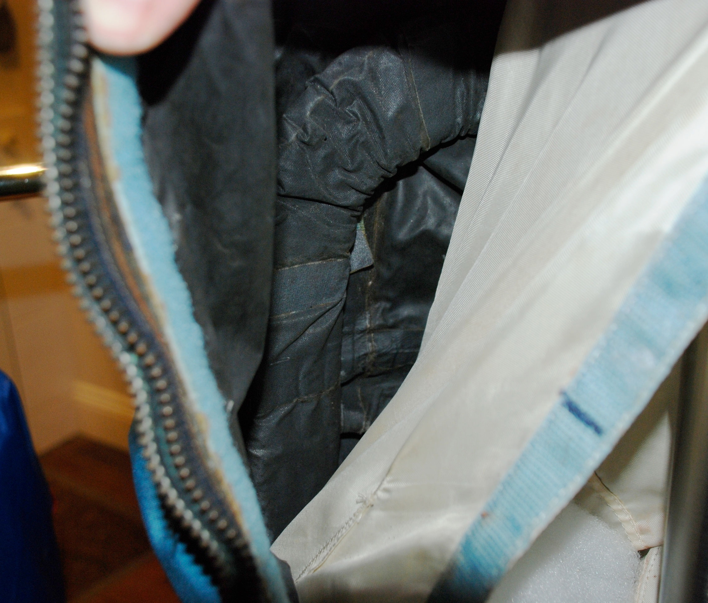
I have two final questions about ventilation ducts. Were they attached on the inner surface of the neoprene coated nylon bladder? To the white liner confort (as on the boot), or a "mix" of the two?Here are two photos sent by Mr David Mather (a few years ago, I'm not sure where they are). One, on the white liner confort: 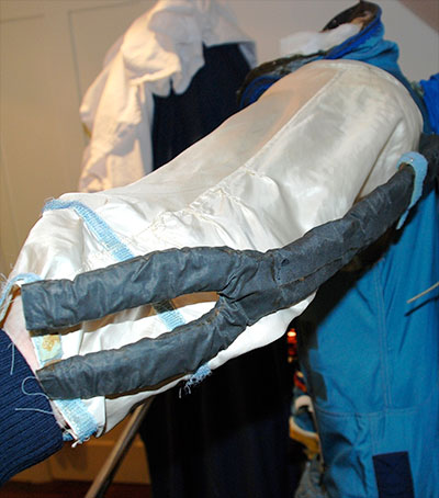 The other apparently on the bladder:  Then for the torso ventilation ducts... Apparently, and this is a deduction on my part, these are not made in the same way as the leg vents. It seems to me that torso channels are permeable so that oxygen can be distributed to the astronaut's chest unlike the others, which must be impermeable to evacuate stale gas. Can anyone confirm what I'm saying? |
Jim Behling
Member Posts: 1911
From: Cape Canaveral, FL
Registered: Mar 2010
|
posted 04-13-2024 10:16 AM
quote:
Originally posted by Apolloman:
...which must be impermeable to evacuate stale gas.
Why do you think that? The chest gets flow from the helmet. |
Apolloman
Member Posts: 225
From: Ledignan, Gard (30), France
Registered: Mar 2009
|
posted 04-13-2024 02:33 PM
The PDF "Apollo Operations Handbook Extra Vehicular Mobility Unit Volume I: System Description CSD-A-789-(1) Apollo 147" from which I drew this image and where it is written: The two inlet gas connectors and the two outlet gas connectors are each interconnected by plenum chambers. The ventilation ducts to the torso area and the head are connected to the inlet connectors. Or, the IV ventilation system is shown in figure I-13. It can be seen from this diagram that there is also only one torso vent duct. 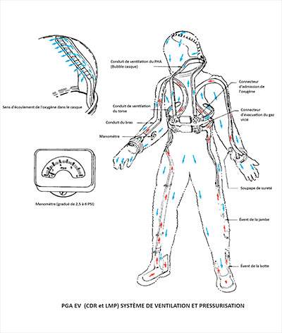 Or: The inlet connector permits the distribution of inlet ventilating gas flow to the helmet, torso ducts, and to the adjacent inlet connect (EV configuration only). The inlet connector has a butterfly diverter valve with two positional modes; OPEN , used for intravehicular operations, and CLOSE, used for extravehicular operations. The position of the valve is identified by a raised projection on the diverter valve knob, horizontal for OPEN, and vertical for CLOSE. In the CLOSE (EV) position, the inlet gas flow is directed to the helmet vent duct and in the OPEN (IV) position, the flow is divided between the helmet vent duct and the torso duct(s). I found the document where it was written out in full: Incoming gas is also supplied from one of the inlet connectors to the torso channels 380 and 382. These channels preferably are pervious to gas along their length so that the gas is distributed to the astronauts torso over substantially the entire length of both the torso channels to which the gas is supplied. |
DG27
Member Posts: 262
From: USA
Registered: Nov 2010
|
posted 04-14-2024 05:20 PM
The torso ducts have holes along the top and bottom edges of the duct for distribution of the inlet gas to the torso area. |
Apolloman
Member Posts: 225
From: Ledignan, Gard (30), France
Registered: Mar 2009
|
posted 04-14-2024 05:24 PM
Okay thank you...If I understand correctly, they are built in the same way and with the same materials as other ventilation ducts, except for the holes drilled in them. But are these ventilation ducts attached to the pressure bladder or to the comfort liner? |
DG27
Member Posts: 262
From: USA
Registered: Nov 2010
|
posted 04-14-2024 05:28 PM
Yes, the outer covering of the torso duct is neoprene coated ripstop nylon with holes punched where needed.The ventilation ducts are attached to the inside of the pressure bladder. The liner is attached to the inside of the bladder with Velcro. |
Apolloman
Member Posts: 225
From: Ledignan, Gard (30), France
Registered: Mar 2009
|
posted 04-14-2024 05:47 PM
What misled me was the photo earlier posted where (unfortunately for me) you can clearly see the ducts on the comfort liner... |
Apolloman
Member Posts: 225
From: Ledignan, Gard (30), France
Registered: Mar 2009
|
posted 04-18-2024 01:40 AM
To finalize my article on the A7L pressure suit, I'm looking for a photo of one of the plenums mounted on the TLSA EV.I know what this part is used for (it connects the intake connectors together and also the exhaust connectors), but I can't find any representation (photo or correct diagram) of it apart from those used in industrial ventilation. Could someone please help me? Thank in advance. |
Apolloman
Member Posts: 225
From: Ledignan, Gard (30), France
Registered: Mar 2009
|
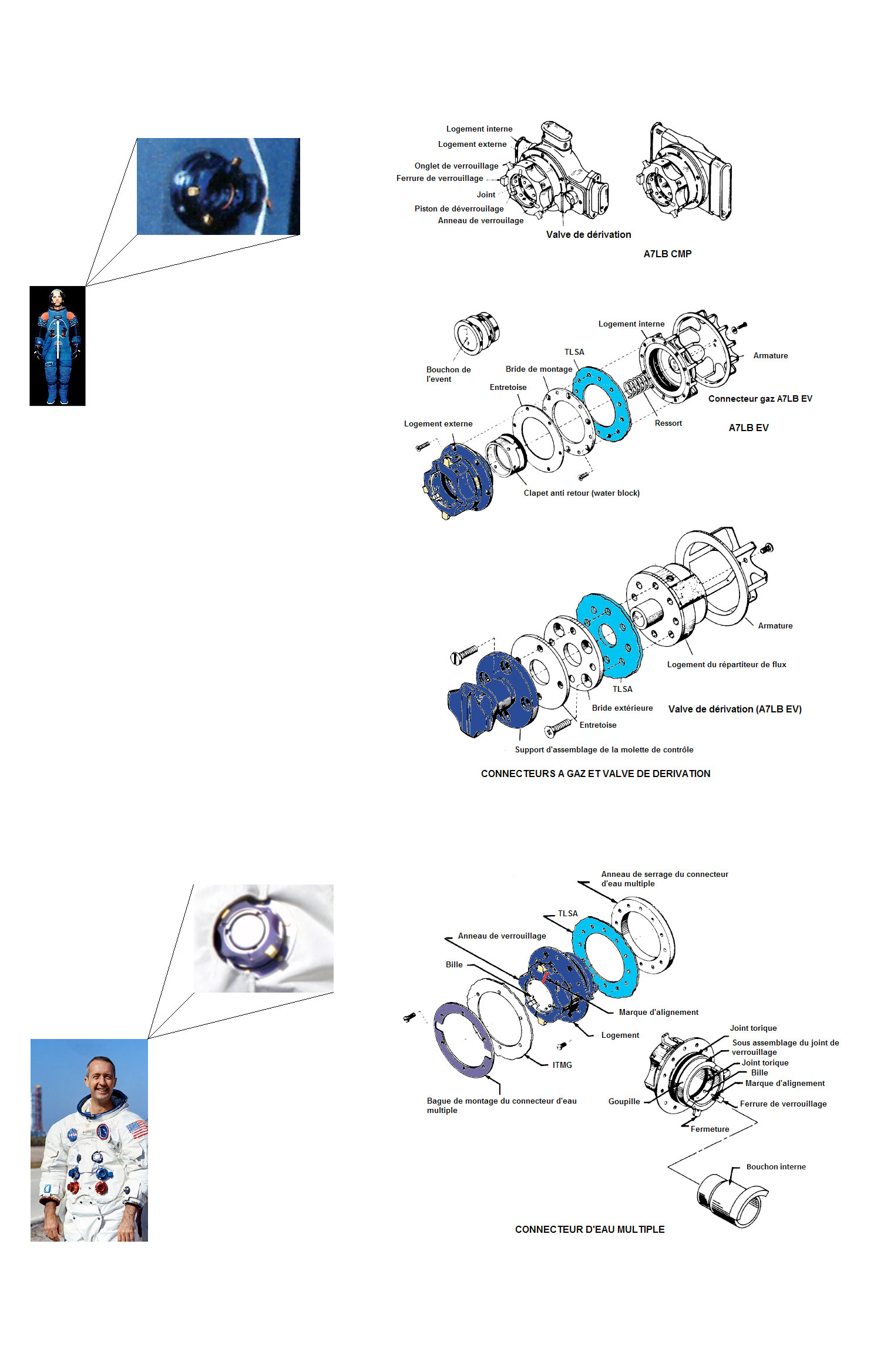
posted 06-02-2024 12:27 PM
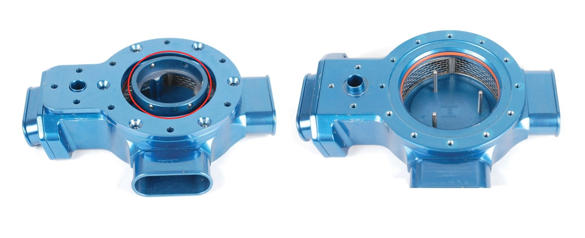
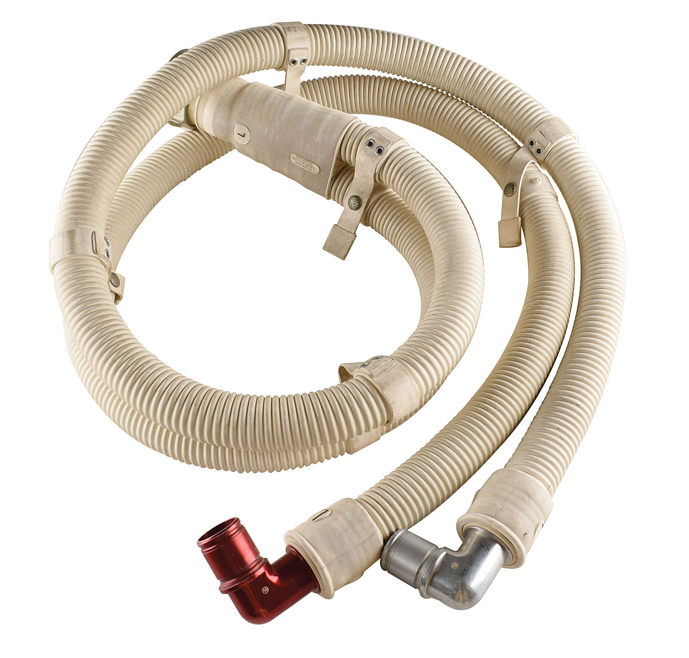
In the first photo could someone tell me what that piece circled in red is and what its role is? It looks like the support on which the oxygen hose connector would rest (second photo)? 
NASA also writes about a part called "spring-loaded water block." What is it? A closing cap like in this picture (in french: bouchon)?  |
Spacehardware
Member Posts: 145
From: Durley
Registered: Jan 2008
|
posted 06-04-2024 03:36 AM
The part circled in red fits inside the suit side connector. It has a red rubber sealing ring at its base. It seals off the connector when no external fitting is attached. Once clear of the internal wall of the connector it slides up and down the three steel pins seen on the chamber on the right in the same picture. When the male connector from, for example, the PLSS is inserted into the suit side valve, the circled part is pushed down by the male part to the base of the chamber, opening the chamber for the flow of gasses. Regarding the spring loaded water block. The closing caps are not spring loaded as far as I know. Never seen one, anyway. Most likely refers to the blue, male part of the water feed from the PLSS (assy 9267) which has a series of small ball bearings around the internal circumference which usually indicates some form of locking system. Just a thought. |
Apolloman
Member Posts: 225
From: Ledignan, Gard (30), France
Registered: Mar 2009
|
posted 06-04-2024 06:40 AM
Thank you for this explanation...If I've followed everything correctly, it's this part that the technicians call "spring-loaded water block" according to this text: The inlet gas connector (fig. I-23) is a flange-mounted ball/lock assembly with an automatic locking and manual unlocking mechanism. A SPRING-LOADED WATER BLOCK, when gas connectors are not used, seals the connector port preventing a flow of gas out of the PGA when pressurized, or a flow of water into the PGA when submerged in water. The hose nozzle cannot be disengaged unless the water block seats and providing a gas seal. A kind of non-return valve... |
Spacehardware
Member Posts: 145
From: Durley
Registered: Jan 2008
|
posted 06-06-2024 03:01 AM
Exactly. Spot on. It's the part labelled 'clapet anti-retour' on one of your exploded views.
|