|
Author
|
Topic: Apollo 11 heat shield plug from CM Columbia
|
holcombeyates
Member Posts: 243
From: UK
Registered: Dec 2010
|
 posted 02-01-2016 10:08 AM
   
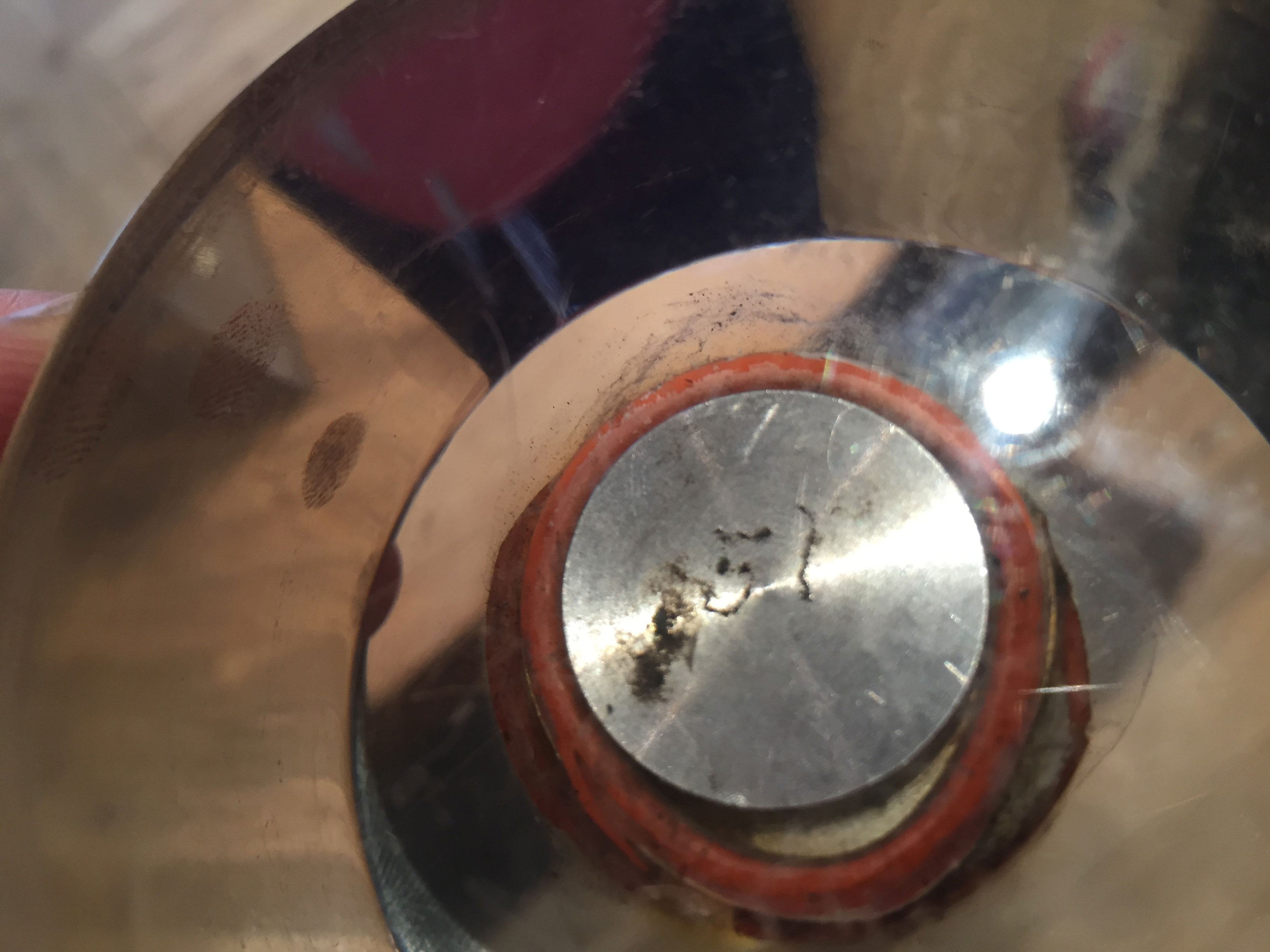
Can anyone please provide some history on how, where from (exactly) and the number of these plugs that were taken from the command module.It's a 1" by 1.25" plug — about as big as I have seen. It is unusual as it has a metal cap at one end with the Number 51 on the metal plate (photo). The charred end is clearly uneven and worn. Looks like it was very much at the "business end" of the heat shield. Most examples are much smaller in cross section. This looks as if it was lifted intact on return. 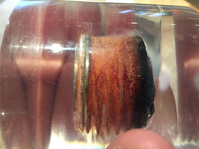 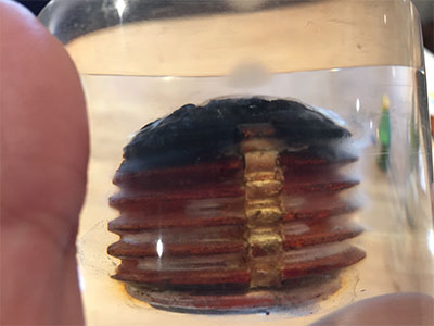

|
David Carey
Member Posts: 782
From:
Registered: Mar 2009
|
posted 02-01-2016 01:13 PM
(From an earlier Apollo 13 thread)From the construction I've been assuming; - these were threaded-in assemblies for covering larger bolt and screw heads or other access points
- the metal plate and O-Ring were integral to the original heat shield thread-in plug
- the damage/obliteration of some of the thread was caused when coring the plug assembly out of the spacecraft.
And to your other comment I'll add one more assumption: - the charred end faced re-entry heat of course and the metal cap faced toward, and perhaps bottomed out on, the bolt/screw/fastener/etc being covered and protected.
|
CMikeW
Member Posts: 89
From: United States
Registered: Apr 2013
|
posted 02-01-2016 09:30 PM
It looks like an Apollo base heatshield ablator plug. There were a large number of them that covered and closed out the bolts that attached the command module heatshield to the command module structure.The material in the groove that is visible in the one picture was RTV, which served to lock the plug in place so it would not back out during a mission. The plugs had a pair of holes that a special pin wrench driver fit into for installation. After the plugs were installed the driver holes were filled with RTV. |
kosmo
Member Posts: 388
From:
Registered: Sep 2001
|
posted 02-02-2016 04:24 AM
From your topic title, you say its from Apollo 11, how do you know this? |
holcombeyates
Member Posts: 243
From: UK
Registered: Dec 2010
|
posted 02-02-2016 08:40 AM
The Lucite is mounted on a wooden plaque that commemorates Apollo 11. This plug is ex the Deke Slayton estate. |
holcombeyates
Member Posts: 243
From: UK
Registered: Dec 2010
|
posted 02-02-2016 08:44 AM
Thanks for the clarification. Understand that they protected the bolts attaching the heat shield. The next question is - how were they able to extract them after the mission when the outer coating would be blistered and heavily charred? Did they have a jig that would allow them to identify the locations accurately? |
mikej
Member Posts: 481
From: Germantown, WI USA
Registered: Jan 2004
|
posted 02-02-2016 06:16 PM
quote:
Originally posted by CMikeW:
There were a large number of them that covered and closed out the bolts that attached the command module heatshield to the command module structure.
The holes in the main heatshield are visible in this Apollo 13 photo. |
holcombeyates
Member Posts: 243
From: UK
Registered: Dec 2010
|
posted 02-03-2016 04:49 AM
Thanks, that's a great photo. Wonder why they needed to remove all the plugs, did this happen on all missions for engineering evaluation? I don't recall seeing this on the back end of Columbia for example.There were obviously a lot of these plugs! I count about 60. Some of these plugs were then divided further into smaller slices. You could probably create about five from each of the single plug sockets. |
space1
Member Posts: 853
From: Danville, Ohio
Registered: Dec 2002
|
posted 02-03-2016 06:09 AM
The holes in the heat shield in that Apollo 13 photo are too large to be associated with this type of plug. Those holes would be bored holes for postflight heat shield evaluation. The plug instead is the type used in the conical heat shield. (The entire exterior of the Command Module was a heat shield.) Look at the rows of small circles on sections of the conical heat shield - around the hatch, around each window, around access doors. Those are the locations of heat shield plugs such as this. There are a few hundred scattered around the conical section. |
David Carey
Member Posts: 782
From:
Registered: Mar 2009
|
posted 02-03-2016 02:04 PM
To the earlier question, I suspect the ablator plug locations were visually obvious even after the charring of re-entry, so no jig needed. See some images in this thread including the paper mentioned therein. Figures 8/9 of the paper are particularly noteworthy. If I have my bearings straight, in all cases the heat shield attach-point ablator plugs have been cored out with something oversized to the original plug diameter; this might explain why they seem too big to be a match. Figure 8 mentioned above doesn't show a thread on the ablator plug body but does possibly show the metal end cap. Smaller Apollo threaded ablator plugs (with no metal cap) appear somewhat regularly, most all with the pair of holes intact. The large samples do not seem to show the twin holes or possibly they've been charred away. My perception is the smaller plugs are generally from the hatch and panel areas on the conical CM crew compartment heat shield as John (space1) mentions. Charring is often subdued if present at all, consistent with the lower heat load. There are also smooth-walled plugs that were probably taken most often from the expanse of the aft heat shield. Note the presence of smaller, more random, heat shield holes — often filled — in some of the photos. I'd appreciate any improvements or corrections to this but here's a take on three primary categories of Apollo flown heat shield sample sources, whether later encased in lucite or otherwise: - Large Threaded: about 1-1/4" diameter threaded ablator plugs with metal cap and RTV O-ring, primarily from the aft heat shield attach points. Usually whole but here was a nice cross-sectioned version.
- Small Threaded: about 1/2" diameter finely-threaded ablator plugs that covered screws under the crew compartment and forward heat shield. Associated with hatches, doors, and access panels.
- Cored/Sawn: Other cored heat shield sections with smooth sides. Removed from the 'field area' of the aft heat shield (and possibly areas of the crew compartment shield?). A 1" diameter core seemed to be common for round samples, and the starting point for semi-circular or pie-shaped sub-samples. Rectangular blocks sawn from the heat shield have also appeared.
To illustrate: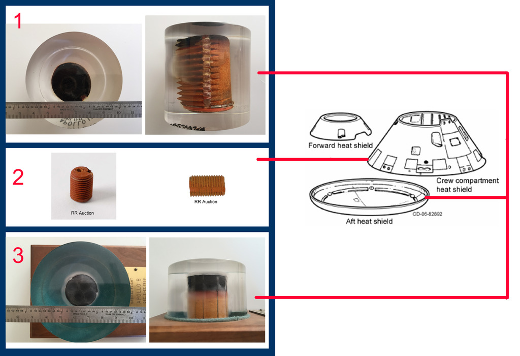 Mercury/Gemini samples seem to fall only into the latter category. A slightly different thread on the heat shield presentation types (vs. sample types) has some great images. |
space1
Member Posts: 853
From: Danville, Ohio
Registered: Dec 2002
|
posted 02-03-2016 05:09 PM
Thank you David for your insights and the links. |
David Carey
Member Posts: 782
From:
Registered: Mar 2009
|
posted 02-03-2016 08:11 PM
Not sure how correct any of that is but fun to try and sort!I noticed the significant difference in plug 'height' between our 'Type 1' Apollo 11 and Apollo 13 examples here. Would it be a function of the variable heat shield thickness per Figure 5 of the above NASA paper and Scott's (Spaceaholic's) related discussion? Might also explain the numbering on the integral metal plates as being for correct circumferential installation over the attachment bolts ringing the aft heat shield. |