Posts: 212 From: Los Angeles, CA, USA Registered: Apr 2019
posted 12-15-2019 01:37 AM
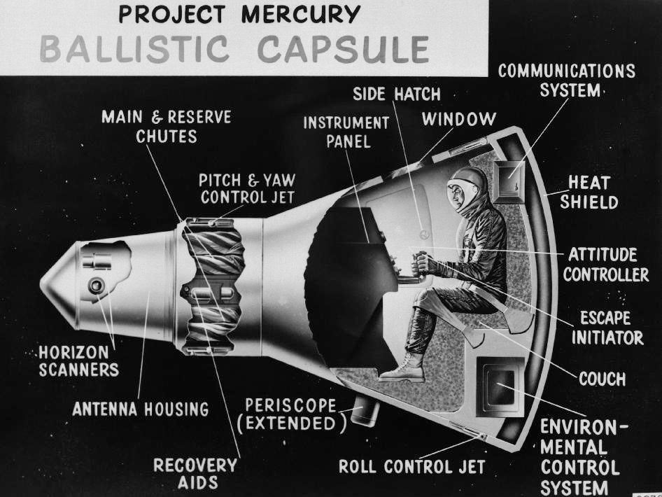
I wanted to double-check if I have the layout of the components inside the nose of the Mercury capsule correct.
First is the nose cap which I believe was ejected right after orbital insertion.
Secondly, after the nose cap was ejected, there was an exposed compartment at he top of the nose of the capsule. In one section of the compartment was the capsule's antenna and in another section was the spacecraft's main parachute, and in another compartment was the spacecraft's reserve parachute. I can't imagine that the parachutes compartment would be allowed to be exposed to space. So was the parachutes compartment stored below the antenna?
Third, after the main parachute had deployed and the spacecraft had splashed down, if the astronaut inside the capsule needed to egress the spacecraft through the neck tunnel inside the spacecraft, then the astronaut would access a hatch at the top of the tunnel. When the hatch was opened, this would create a passage to the outside of the spacecraft.
If so, what happened to the parachute compartment when the hatch was opened? Would the parachute compartment fall into the sea and take the main parachute with it? Also has anyone seen what the hatch and hatch handle to the bulkhead looked like?
space1 Member
Posts: 866 From: Danville, Ohio Registered: Dec 2002
posted 12-15-2019 07:29 AM
If you have not already done so, carefully study the Project Mercury Familiarization Manual, which you can find here. I think most of your questions will be answered there.
mercsim Member
Posts: 230 From: Phoenix, AZ Registered: Feb 2007
posted 12-23-2019 09:01 AM
The "nose cap" housed the main antenna, horizon scanners, and drogue parachute and is often referred to as the Antenna Fairing. It also had a small flap that deployed after the tower jettison to stabilize it during re-entry and certain abort modes.
You can download for free and make a paper model of the Mercury nose cone (along with the rest of the spacecraft) from my website.
And as mentioned, the familiarization guide will give you more info if needed.
Lou Chinal Member
Posts: 1335 From: Staten Island, NY Registered: Jun 2007
posted 12-25-2019 07:10 AM
Both the main and reserve parachutes were housed in neck below the drogue. The reserve was jettisoned about one minute after landing.
oly Member
Posts: 1011 From: Perth, Western Australia Registered: Apr 2015
posted 12-27-2019 07:54 AM
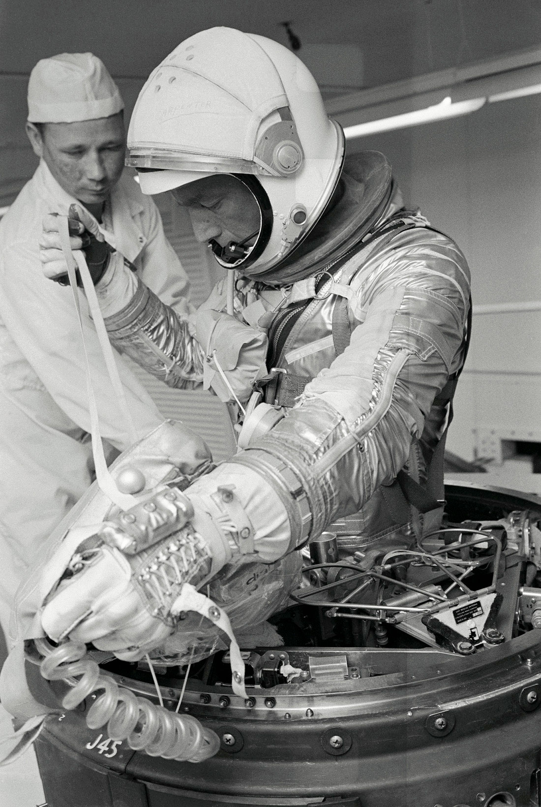
This photo via Space.com shows:
In the White Room at Cape Canaveral in Florida, Project Mercury astronaut Scott Carpenter trains on how to exit the craft through the top. He holds the 'man line' attaching the survival kit to the astronaut in case of a contingent landing. The bag holding the life vest is visible around Carpenter's neck.
Explorer1 Member
Posts: 212 From: Los Angeles, CA, USA Registered: Apr 2019
posted 12-28-2019 04:18 PM
Is the "man line" what is in Carpenter's right hand or is it the coiled chord in Carpenter's left hand? And if the coiled chord is something else, any idea of what it is?
And there is a metal grid that is next to Carpenter's waist. Any idea if that flips up and backward so that it is outside of the neck of the capsule thereby giving the astronaut more room for getting out of the neck of the capsule?
quote:Originally posted by Lou Chinal: The reserve was jettisoned about one minute after landing.
Any idea and what altitude or how long before splashdown that the landing bag was deployed?
Also the main parachute apparently remained attached at splashdown (as in the case of Liberty Bell 7). Is that true? That seemed like a really bad idea as it would fill with water and weigh down the capsule. I am thinking that has to be a mistake because the capsules were hooked onto and transported by helicopter without the parachute attached. Any comments?
oly Member
Posts: 1011 From: Perth, Western Australia Registered: Apr 2015
posted 12-28-2019 05:31 PM
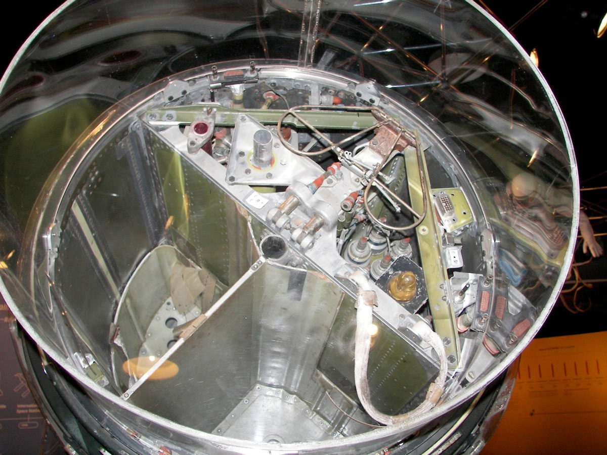
This photo of Scott Carpenter's Aurora 7 (taken by Richard Kruse in 2008) shows additional detail of the Mercury capsule nose section.
Explorer1 Member
Posts: 212 From: Los Angeles, CA, USA Registered: Apr 2019
posted 04-12-2020 09:40 AM
The Mercury spacecraft's antenna was stored in the tip of the nose cone. The antenna was attached to a hinged flap and when the antenna was deployed, the flap swung open on its hinge and flipped outward and away from the nose cone taking the antenna with it. The antenna was then in its operational position with its small dish facing away from the spacecraft.
During reentry was the antenna retracted back into its stowed position on top of the nose cone? Or was it left in its deployed position?
Also were the antennas ever deployed on the MR-3 and MR-4 flights?
oly Member
Posts: 1011 From: Perth, Western Australia Registered: Apr 2015
posted 04-13-2020 09:55 AM
Which antenna are you referring to?
Explorer1 Member
Posts: 212 From: Los Angeles, CA, USA Registered: Apr 2019
posted 04-16-2020 01:49 AM
I am referring to the externally mounted antenna that is on the nose of the capsule.
oly Member
Posts: 1011 From: Perth, Western Australia Registered: Apr 2015
posted 04-16-2020 02:33 AM
The antennas generally needed to be mounted outside the structure of the capsule because the metal airframe acts like a Faraday Cage, shielding radio signals from passing through. Many of the antennas needed post re-entry were housed under the "nose cone" (its official name was antenna fairing).
Housed behind the antenna fairing were the HF recovery antenna, UHF decent and recovery antenna, and a UHF beacon antenna, among other items.
The HF recovery antenna was a whip-style antenna that can be seen in some recovery film and was cut away by the rescue helicopter crew using special shears to prevent the antenna damaging the helicopter of injuring a crew member during winching operations.
The UHF decent and recovery antenna was a double hoop design that can be seen in the above image.
Both antennas were stowed behind the antenna fairing during re-entry, the fairing was jettisoned during decent, before parachute deployment (the fairing deploy also deployed the drogue chute).
quote:Originally posted by Explorer1: During reentry was the antenna retracted back into its stowed position on top of the nose cone? Or was it left in its deployed position?
Were the antennas ever deployed on the MR-3 and MR-4 flights?
No and yes.
[Edited April 19 2020]
mercsim Member
Posts: 230 From: Phoenix, AZ Registered: Feb 2007
posted 04-18-2020 04:47 PM
The Antenna Fairing did not house all those antennas. Some of them were in the recovery section. The familiarization manual will describe in detail what was where.
oly Member
Posts: 1011 From: Perth, Western Australia Registered: Apr 2015
posted 04-18-2020 08:01 PM
Thanks, now corrected.
mercsim Member
Posts: 230 From: Phoenix, AZ Registered: Feb 2007
posted 04-21-2020 06:46 PM
Just a minor correction... The fairing deploy did not deploy the drogue. The drogue was inside the fairing and deployed first after re-entry. The fairing was jettisoned around 10,600 ft when the main came out. There is some good beach abort footage showing the entire sequence, although the altitudes are not normal. There are also a few photos of the fairing under parachute. I seem to remember one with MR-3 on it.
Lou Chinal Member
Posts: 1335 From: Staten Island, NY Registered: Jun 2007
posted 04-23-2020 05:10 AM
Yes, there is that famous MR-3 photo that was taken out of the right hand porthole by an auto camera. The black dot below the canopy is the deployment bag of the maim chute. It was attached via a 30 foot riser to the antenna canister.
oly Member
Posts: 1011 From: Perth, Western Australia Registered: Apr 2015
posted 04-23-2020 06:32 AM
The MR-1 launch failure film shows the fairing, drogue, and main chute deploy, and there may even be a glimpse of the reserve chute deploy within the last few frames.
Explorer1 Member
Posts: 212 From: Los Angeles, CA, USA Registered: Apr 2019
posted 04-23-2020 07:53 PM
The main communications antenna of the Mercury capsule was attached to a flap that was folded flat down on the blunt nose of the capsule. When the capsule was in orbit, the flap would flip outward like a door on a hinge and this would take the antenna along with it and position the antenna in the direction of open space and also position the antenna off to one side of the capsule into open space. So the antenna was effectively positioned out of alignment from the nose of the capsule.
The antenna would presumably burn off during reentry if it remained in the deployed position. So was the main antenna retracted back into a closed (undeployed) position before reentry?
oly Member
Posts: 1011 From: Perth, Western Australia Registered: Apr 2015
posted 04-24-2020 03:11 AM
quote:Originally posted by Explorer1: The main communications antenna of the Mercury capsule
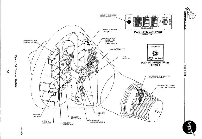
Which communications antenna are you classifying as the "main antenna"? From the Mercury Familiarization Manual (SEDR 104), Chapter 12-6:
The voice communications, telemetry and beacon receivers and transmitters, with their various frequencies and types of outputs require an antenna system with wide capabilities. Therefore, five antennas are used to fulfill the entire mission requirements. A main Bicone antenna and a Retro Package HF Dipole Antenna is used for the major portion of the mission. During re-entry, the Bicone antenna must be jettisoned to allow main parachute deployment. The HF Dipole is jettisoned with the retro package. To replace the UHF function, a compact UHF Recovery antenna is automatically placed in operation at bicone separation. Upon landing, an HF Recovery Whip Antenna and an Aux. UHF Beacon Antenna are extended to permit HF and UHF operation. Through-out the entire mission, C- and S- Band antennas are provided for operation of the radar beacons. Antenna switching and multiplexing are performed automatically by the RF circuitry.
mercsim Member
Posts: 230 From: Phoenix, AZ Registered: Feb 2007
posted 04-24-2020 09:03 AM
I'm not sure where Explorer got that information but it's not very accurate. The flap was a destabilizing flap for certain abort modes to help keep the capsule orientated properly. It was deployed automatically when the tower jettisoned.
Interesting fact, a little pyro cutter cut through a piece of rope to allow its loaded spring to pop it out. It may have got crispy during regular re-entry but it didn't matter.
Oly's clip from the Familiarization Manual describes the antennas really well. The manual has really nice drawings of all of them and they can all be seen in photographs. I realize it can be a bit dry but is only 500 pages or so. If you really want to know about the Mercury capsule and its operation, it's all there.
Many people get confused about the main bicone antenna. It's literally a cone of metal that allows best operation radially. It resides under the large white band on the antenna fairing, hence the name.
Here is a nice paper model of the antenna fairing. It's an exact 1/4 scale replica made from many sources, one of which was unprecedented access to photograph the inside of one of the few surviving ones. There are few nice drawings in the Familiarization Manual of it also.
Explorer1 Member
Posts: 212 From: Los Angeles, CA, USA Registered: Apr 2019
posted 04-24-2020 11:30 AM
I went to the link you provided and what I have been assuming is the main antenna is pictured on the page you provided.
In the photograph below the title "Antenna Fairing," there is the nose cone that appears in front of the others to the left. There is a white apparatus that looks something like a dish antenna on a boom. It's completely flat and is attached to the flap. Are you saying this is not the main antenna?
oly Member
Posts: 1011 From: Perth, Western Australia Registered: Apr 2015
posted 04-24-2020 06:17 PM
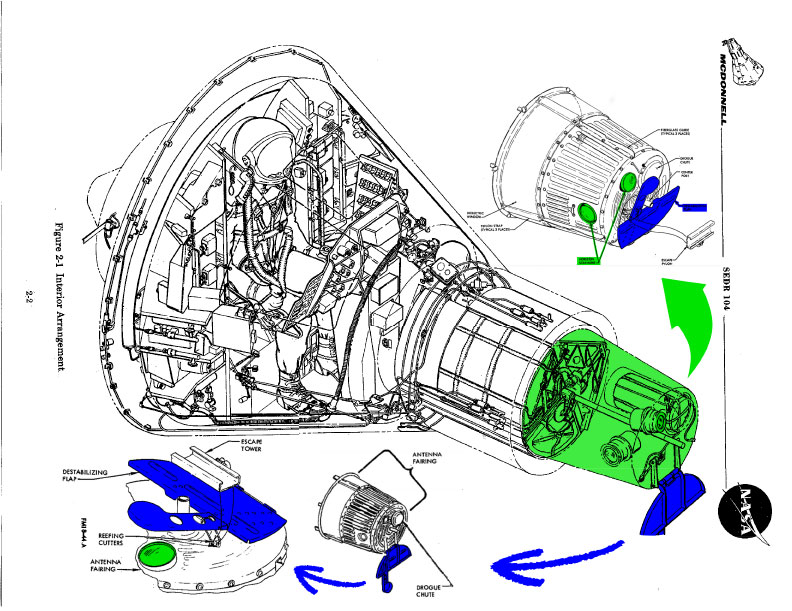
There is NO single main antenna, refer to the multiple posts above. The item you are referring to is a cover for the forward looking Horizon Scanner, part of the Stabilization and Control System.
As mentioned previously, all of this information is available in the Mercury Familiarization Manual, available for download on the internet. I have compiled a composite illustration (taken from the Famil Manual) to help identify the Horizon Scanner (Green) and the cover attached to the Destabilization Flap (Blue).
mercsim Member
Posts: 230 From: Phoenix, AZ Registered: Feb 2007
posted 04-24-2020 06:20 PM
It's a fiberglass cover to protect the horizon scanner when the tower goes. Then the cutter fires that cuts the rope allowing the flap to deploy. If an abort occurred in a certain part of the atmosphere, they were concerned the capsule would not orient properly. The flap moves the center of pressure just enough to avoid this. And it protected the scanner. Once a certain altitude was reached, it wasn't necessary and was along for the ride. Some early documentation indicates it was also to aid in normal re-entry but was later found not necessary. It talks about it somewhere in "This New Ocean."
The Bicone antenna is considered the "main" radio antenna. The white band is a dialectric between the capsule and top of fairing. It has foam in there which you can see in the Familiarization manual. It was to stabilize the structure and provide some vibration damping. A side benefit was it allowed the fairing to float fairly well. A few were recovered. There are photos of the one from Liberty Bell being examined on the deck of a ship.
You could print out Card_Antenna4 from the page linked above and fold one up yourself. It's 1/4 scale but you could easily scale it up to make a full size one if you wanted.
Explorer1 Member
Posts: 212 From: Los Angeles, CA, USA Registered: Apr 2019
posted 04-24-2020 06:58 PM
The early Mercury spacecraft had a different kind of nose cone. It was pointed. This was later replaced with a blunt end nose cone. What prompted the change and what was the first Mercury spacecraft to use the blunt end nose cone?
mercsim Member
Posts: 230 From: Phoenix, AZ Registered: Feb 2007
posted 04-24-2020 07:21 PM
It was never pointed. I have mentioned here before it sometimes looks that way and cheap models (toys) are often done that way. What you see as a point is a conical cover attached to the escape tower to help protect the antenna fairing during tower jettison.
There are several videos online of Mercury development. The familiarization manual went through several versions but the earliest one you can find on the net was printed in 1959. It's clearly seen in the drawings in the familiarization manual.
Take advantage of the lockdown and sit and read the familiarization manual. At the very least, look at ALL of the drawings and read the captions. Also, the Spacecraft Films' DVD on Project Mercury is a must have for any Mercury enthusiast.
And I'm a bit partial, but there is an entire education in building the 1/4 scale paper model. Even if you throw it together in all white, you'll learn a ton about the capsule.
The point is there and the aerodynamic wedge, which is also part of the escape tower, is there. The build instructions talk a bit about it.
Explorer1 Member
Posts: 212 From: Los Angeles, CA, USA Registered: Apr 2019
posted 04-24-2020 08:56 PM
Thank you again. I have a great respect for the model builders who have delved into the fine details of the spacecraft, which is why I am posting here. At some point when I have the time (I am engaged in numerous projects right now) I will look at the familiarization manual.
I do have one more question regarding this. If I am understanding you correctly you are saying that the pointed nose cone is not a part of the capsule but a conical cover that is attached to the launch escape system and fits over the blunt nose cone. Is this correct?
But this NASA drawing from 1959 shows the pointed nose cone as exactly that, a nose cone and not necessarily part of the escape tower. Can you share your estimate of what we are seeing in this diagram or why it was drawn this way?
mercsim Member
Posts: 230 From: Phoenix, AZ Registered: Feb 2007
posted 04-24-2020 10:50 PM
It's just an editing hack by some graphics person. I think that artwork once included the escape tower and the person that edited it didn't know what they were looking at. You can also see the horizon scanner pointing forward which clearly wouldn't have worked if covered.
Explorer1 Member
Posts: 212 From: Los Angeles, CA, USA Registered: Apr 2019
posted 04-25-2020 12:28 AM
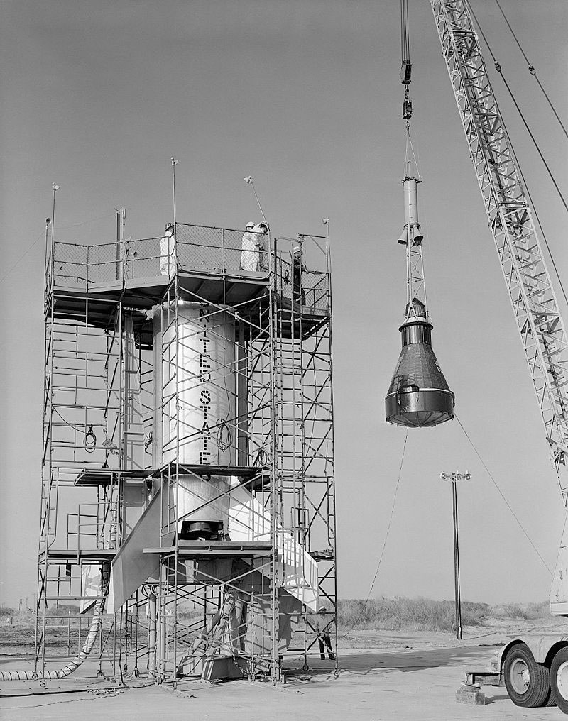
I'd like to share one more picture with you and get your feedback. It's a picture of the Little Joe 1 Mercury capsule being hoisted into position to be mated with its booster. The conical cape is on the nose of the capsule but there is no launch tower. So what's going on here in this picture?
Robert Pearlman Editor
Posts: 43709 From: Houston, TX Registered: Nov 1999
posted 04-25-2020 12:38 AM
Maybe you missed it because of the similar shades of gray between it and the sky, but the escape tower is installed in that photo.
oly Member
Posts: 1011 From: Perth, Western Australia Registered: Apr 2015
posted 04-25-2020 03:41 AM
This image (from the album discussed here) of a recovered antenna fairing shows that there is no cone shape to the top of the fairing.
Explorer1 Member
Posts: 212 From: Los Angeles, CA, USA Registered: Apr 2019
posted 04-25-2020 04:22 AM
Thank you for pointing the tower out and thank you for delving into an interesting detail. I have come across a number of drawings (some associated with models) with the conical cap depicted as part of the capsule.
Also the diagram we spoke about earlier was actually an official NASA drawing and was shown to the media at a press conference I believe in 1960. And the drawing shows up in several official NASA histories. So it is very disturbing for NASA of that time to endorse the conical cap as an accurate depiction of the capsule. Any comments on this?
Last question about this cap. Is it its own independent piece or is is actually part of the escape tower?
Also my thought had been that the early spacecraft that appeared to have this conical cap, had it for aerodynamic purposes but that it was ejected in space to expose the blunt end. But it appears that it was pulled away with the escape tower.
And not to belabor this point (no pun intended) but the confusion over the conical cap even goes back to the reentry configuration models of the Mercury capsule. There are drawings and models made by NASA to represent the Mercury capsule's shape and the Space Task Group had narrowed the choice of capsule configurations down to four variants. Variant "C" had a pointed nose (essentially the conical cap). And Variant "D" had a blunt nose. Variant D was ultimately chosen.
Jim Behling Member
Posts: 1502 From: Cape Canaveral, FL Registered: Mar 2010
posted 04-26-2020 08:38 AM
quote:Originally posted by Explorer1: So it is very disturbing for NASA of that time to endorse the conical cap as an accurate depiction of the capsule.
There is always differences between PR material and the actual hardware.
mercsim Member
Posts: 230 From: Phoenix, AZ Registered: Feb 2007
posted 04-26-2020 09:40 AM
quote:Originally posted by Explorer1: At some point when I have the time I will look at the familiarization manual.
There are all your answers.
NavyPilot Member
Posts: 42 From: Registered: Nov 2015
posted 04-26-2020 10:43 AM
Conical cap on MA-4 and on LJ-1 (c) 1959.
mercsim Member
Posts: 230 From: Phoenix, AZ Registered: Feb 2007
posted 04-26-2020 05:19 PM
As said before, its part of the escape tower. Just Google it an you will find lots of photos.
Here is a video of the MA-3 abort. It's all cool but you can see the peroxide dumping when the drogue deploys. You can also see the antenna fairing separate and pull the main out. After a few minutes, you can see the tower coming down and passing the capsule. There are some shots of the tower on the beach but the sheet metal that made up the 'cone' is all but destroyed.
In this video, you can see the 'cone' clearly around 4:30 when they stack the tower.
NavyPilot Member
Posts: 42 From: Registered: Nov 2015
posted 04-27-2020 12:19 PM
Excellent video references, especially the second one.
Posts: 212 From: Los Angeles, CA, USA Registered: Apr 2019
posted 04-27-2020 10:10 PM
Any thoughts why they had the usual method (with a cutter) to deploy the destabilizing flap?
oly Member
Posts: 1011 From: Perth, Western Australia Registered: Apr 2015
posted 04-28-2020 03:58 AM
Because during the launch phase the astronaut had an extremely high workload and it was thought that no amount of training could get the crew ready to untie the rope at the exact moment required.
Lou Chinal Member
Posts: 1335 From: Staten Island, NY Registered: Jun 2007
posted 05-03-2020 11:43 AM
The spacecraft being lifted up on the Little Joe is #14.


 posted 12-15-2019 01:37 AM