|
Author
|
Topic: Blue protective covering on Apollo CM
|
oly
Member Posts: 1436
From: Perth, Western Australia
Registered: Apr 2015
|
 posted 09-27-2018 06:17 AM
   
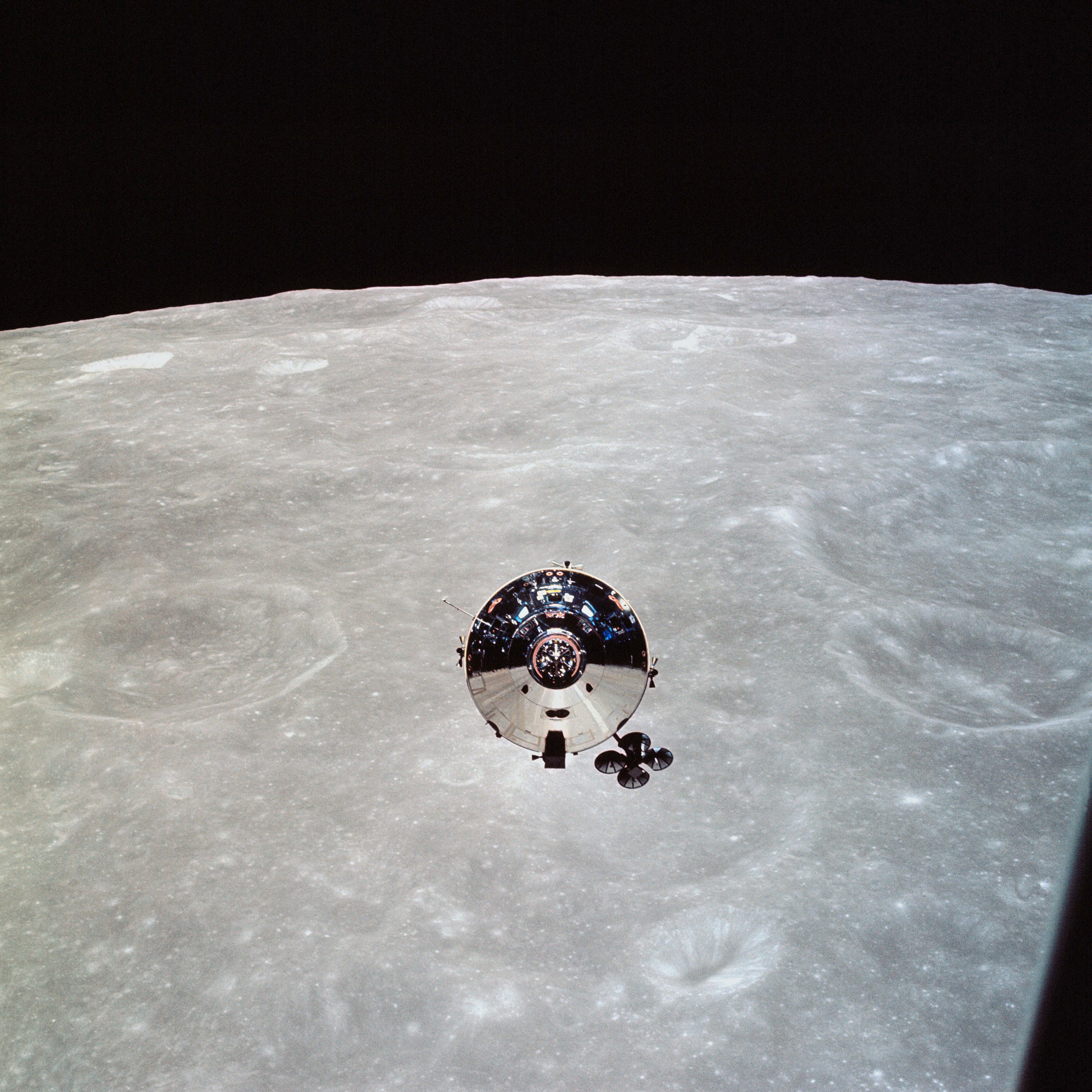
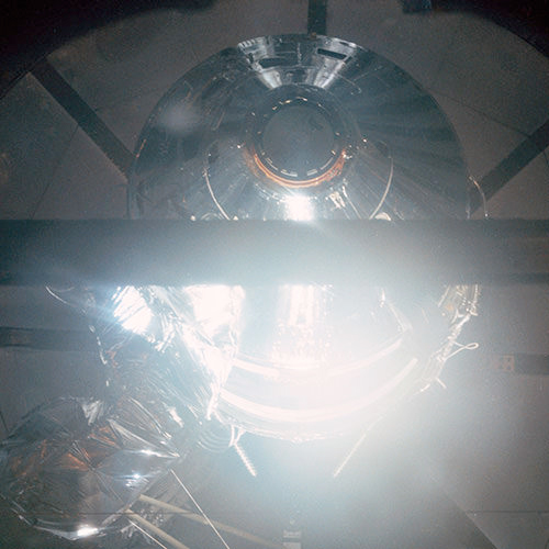
Just by the nature of the reflective surface, many images of the command module show a reflection of the surroundings.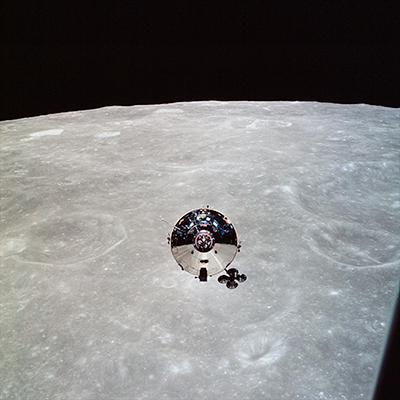 The moon or Earth can be seen in many images and even on Earth. 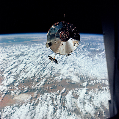 
There are not many images taken from the Soyuz spacecraft of the Apollo command module that clearly show fine detail that can be found with other missions. |
LM-12
Member Posts: 3723
From: Ontario, Canada
Registered: Oct 2010
|
posted 09-27-2018 06:56 AM
Photo S75-26904 is similar to the image posted earlier, but it gives a better view of the CM side opposite the hatch. I do not see any painted areas in either photo.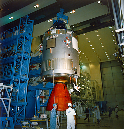 |
LM-12
Member Posts: 3723
From: Ontario, Canada
Registered: Oct 2010
|
posted 09-28-2018 08:24 AM
The altitude tests for the command module preceded the docking tests. The Apollo Soyuz Mission Evaluation Report has the modification and checkout history of the CSM-111 spacecraft. See figure C-1 and figure C-2. CSM-111 prior to August 1972: - March 1967 - start of fabrication
- March 1970 - completion of fabrication
- July 1972 - plant storage completed
|
oly
Member Posts: 1436
From: Perth, Western Australia
Registered: Apr 2015
|
posted 09-28-2018 08:01 PM
CSM-111 was in storage, testing or modification work for some time, Perhaps during this there was dome deterioration or defect found with the Kapton tape that required removal an replacement. The forward heat shield would have been installed/removed during transport and to gain access to the items beneath. I guess the maintenance logs exist somewhere. |
LM-12
Member Posts: 3723
From: Ontario, Canada
Registered: Oct 2010
|
posted 09-28-2018 10:07 PM
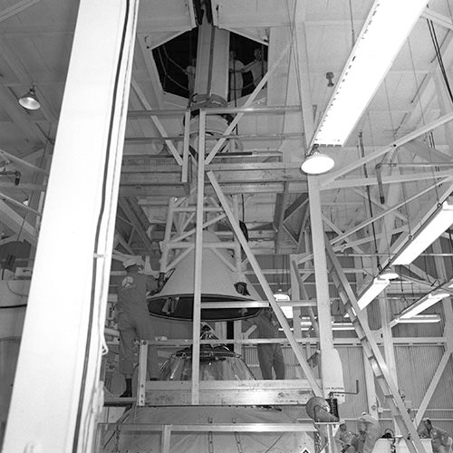
Black and white photo KSC-75P-0015 (linked earlier) shows the command module, with the docking module above, in the altitude chamber. There is no blue film covering the forward heat shield area above the CM hatch.I did find some imagery (must have been taken later) that does show blue film above the CM hatch. The CM and DM are docked in the altitude chamber. |
Mike Dixon
Member Posts: 1625
From: Kew, Victoria, Australia
Registered: May 2003
|
posted 09-29-2018 01:03 AM
Okay... dumb question. Why the red shroud wrapped around the SM engine bell? |
oly
Member Posts: 1436
From: Perth, Western Australia
Registered: Apr 2015
|
posted 09-29-2018 02:17 AM
These are protective blankets to prevent damage and contamination during shipping and handling. |
LM-12
Member Posts: 3723
From: Ontario, Canada
Registered: Oct 2010
|
posted 09-29-2018 03:33 AM
Thermal control tape is mentioned in a list of significant hardware replacements in this ASTP Flight Readiness Review Board document from JSC. See page 163. ITEM - thermal control tape
FAILURE - cover film adhesionITEM - BMAG
FAILURE - stiction test What is BMAG? |
oly
Member Posts: 1436
From: Perth, Western Australia
Registered: Apr 2015
|
posted 09-29-2018 07:04 AM
Body-Mounted Attitude Gyro. The Body Mounted Attitude Gyros, or BMAGs, help to back up to the IMU. The two assemblies are capable of detecting the spacecraft's rate. |
oly
Member Posts: 1436
From: Perth, Western Australia
Registered: Apr 2015
|
posted 09-29-2018 08:23 AM
quote:
Originally posted by LM-12:
Thermal control tape is mentioned in a list of significant hardware replacements in this "ASTP Flight Readiness Review Board".
Thanks for posting a link to the review board document.The thermal control tape may well be the item in question. If the dates align with images of the time, you may have found an excellent lead. I also found the list of re-flown items that were planned to be used during Skylab and ASTP missions, itemised on pages 129-144 interesting. |
LM-12
Member Posts: 3723
From: Ontario, Canada
Registered: Oct 2010
|
posted 09-29-2018 11:13 AM
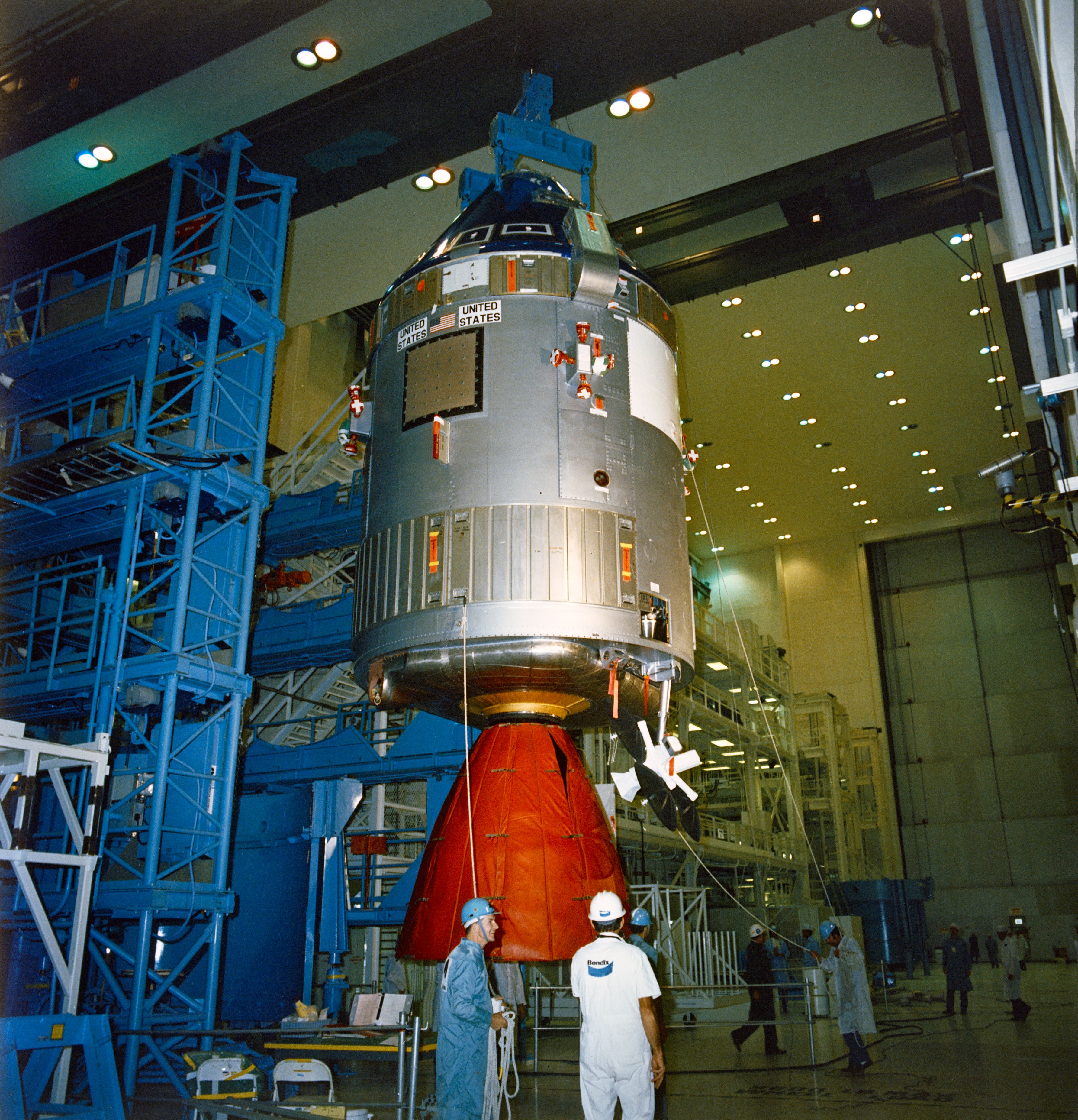
I did notice that re-flown list. Very interesting indeed. It even mentions the CSM that each re-used item previously flew on.The 3-5-75 date on page 163 is the same date as Ed's photo of the CSM being prepared for the CSM/SLA mate in the MSOB High Bay. |
LM-12
Member Posts: 3723
From: Ontario, Canada
Registered: Oct 2010
|
posted 09-30-2018 10:22 AM
quote:
Originally posted by LM-12:
The blue film appears to have been removed from the CM hatch area
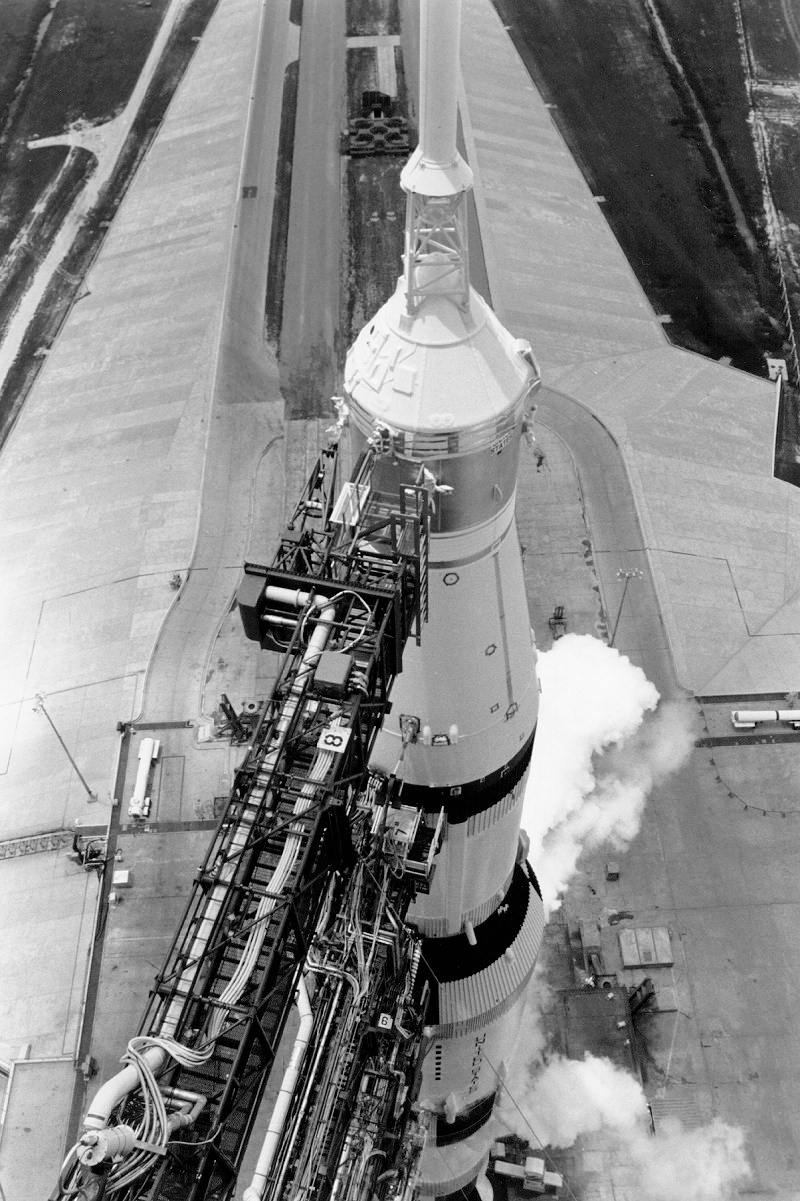
Here is another Apollo 11 photo (dated July 12) taken at the pad that shows the blue film removed from the CM hatch area. Interesting to see the CM hatch area and BPC when the White Room is retracted. 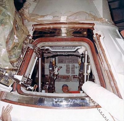 |
Fra Mauro
Member Posts: 1739
From: Bethpage, N.Y.
Registered: Jul 2002
|
posted 10-02-2018 08:56 AM
I guess that's a pad tech inside Columbia. I'm amazed at how detailed this thread has become. |
LM-12
Member Posts: 3723
From: Ontario, Canada
Registered: Oct 2010
|
posted 10-02-2018 10:16 AM
quote:
Originally posted by heng44:
But apparently the BPC can be partially removed at the launch pad. That would mean the blue film can be removed just prior to launch, although on some flights it looks as though it was done before the CDDT.
The aft BPC is installed for the CDDT events, so wouldn't it make sense to remove the blue film before the CDDT (like Apollo 11) so that the aft BPC would not have to be removed and installed again? Like the Apollo 9 CDDT also.  |
LM-12
Member Posts: 3723
From: Ontario, Canada
Registered: Oct 2010
|
posted 10-02-2018 09:51 PM
The blue film was still on the Apollo 11 command module when the crew did their emergency egress walk-through test and CCFF on June 10. |
Marc05A
Member Posts: 40
From: Reims, France
Registered: May 2009
|
posted 10-03-2018 01:54 PM
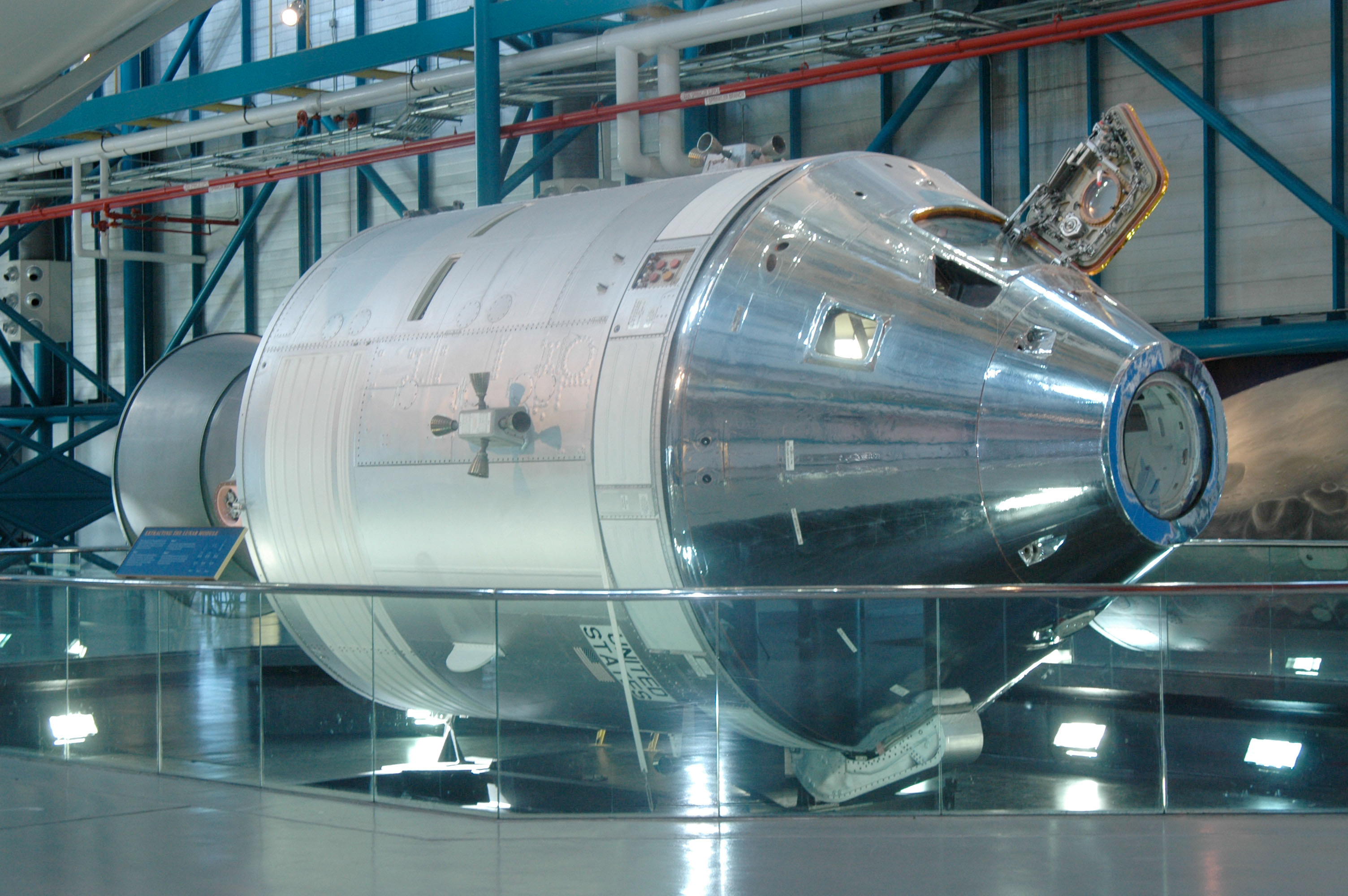
Is the CM-119 exhibited at the KSC Saturn V Visitor Center covered with the original silver-colored Kapton tape? |
oly
Member Posts: 1436
From: Perth, Western Australia
Registered: Apr 2015
|
posted 10-03-2018 02:25 PM
This page has images of CSM-119 when it was painted like the Skylab CSMs. I do not know if the current finish is Kapton or just aluminium tape. |
LM-12
Member Posts: 3723
From: Ontario, Canada
Registered: Oct 2010
|
posted 10-03-2018 08:53 PM
When CSM-119 arrived at the Visitor Center, the CM was painted like a Skylab command module. |
oly
Member Posts: 1436
From: Perth, Western Australia
Registered: Apr 2015
|
posted 10-04-2018 09:28 AM
To follow up on the CSM-119 at the KSC Visitor Complex, the command module was painted like the Skylab CM because it was modified into a standby/rescue vehicle for the last Skylab and ASTP missions. At the end of Skylab, ASTP, it was donated to the Smithsonian, who loaned it to the visitor centre.As the Kapton reflective tape was expensive, it does not seem logical that the spacecraft was covered in Kapton, and then have the blue protective coating removed. Because the Kapton tape was easily damaged, and the highly reflective surface would easily oxidize over time, It would seem more logical that it was replaced with a material better suited for public display and regular cleaning. This photo is the best I could find to show details of the tape, found here. There is also some additional information available here. |
LM-12
Member Posts: 3723
From: Ontario, Canada
Registered: Oct 2010
|
posted 10-04-2018 09:42 AM
The Skylab 4 command module is on display at the National Air and Space Museum. What looks like thermal tape can be seen on the lower part of the crew compartment heat shield near window 5. I suppose prior to launch there was a blue protective film covering that area, but I have not seen any photos showing that.Photo KSC-73P-59 shows the Skylab 4 CM arriving at KSC with white and silver paint only, so it would seem the tape was applied sometime after that at KSC. The tape was not applied in the altitude chamber in the MSOB, because no tape is seen on the command module when the CSM was mated to the SLA. 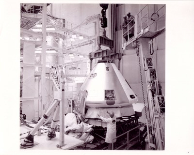 |
LM-12
Member Posts: 3723
From: Ontario, Canada
Registered: Oct 2010
|
posted 10-05-2018 10:10 AM
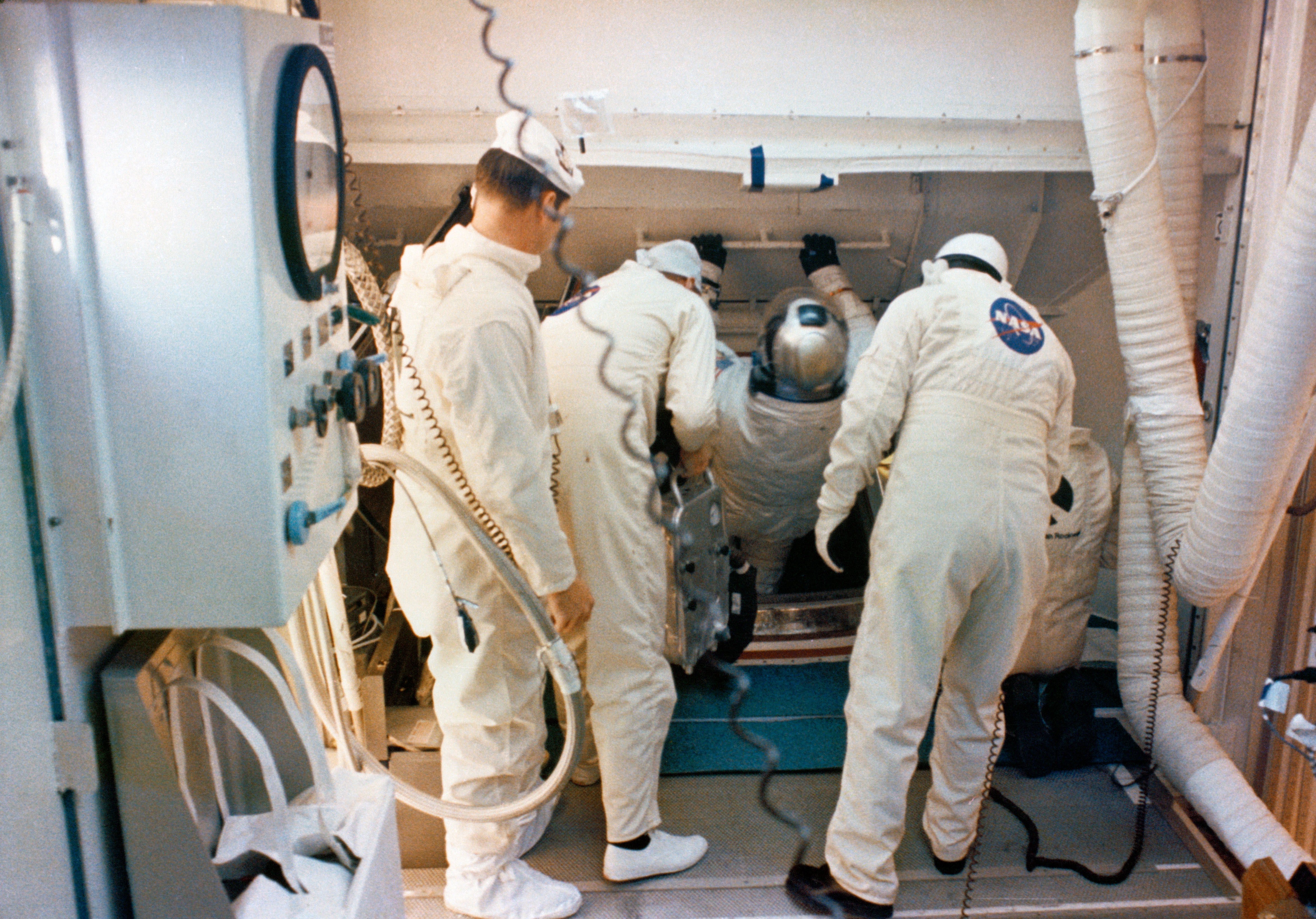
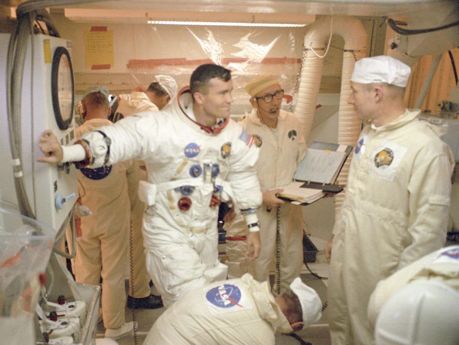
The blue film may still have been on the CM when the Apollo 13 CDDT took place. That must be Lovell behind Guenter Wendt. A blue area can be seen on the CM near the red stripe on Lovell's suit leg.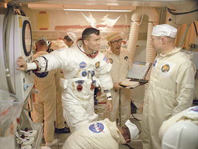 |
oly
Member Posts: 1436
From: Perth, Western Australia
Registered: Apr 2015
|
posted 10-05-2018 09:41 PM
From what can be found in the lunar mission images, the blue film was left on as long as possible prior to launch. I do not know how difficult the removal of the tape was, I imagine it was a laborious task that took some time, as each strip of silver tape would need to be inspected for integrity, and any repair done as needed, so the task would need to be completed and checked off,Where in the pre-launch countdown sequence this was done would be interesting to know, some assumptions, such as prior to the removal of the MSS, loading pyro and batteries come into consideration. The integrity of the reflective surface for non-lunar missions would not be of such high importance, as the spacecraft did not need a BBQ roll manoeuvre for thermal conditioning, and spent about as much time in sunlight as shadow during Earth orbit. This may have changed the priority or order of things during countdown process. Does anyone have access to pre-launch schedules of lunar missions that identify work done in this period that they could share? |
LM-12
Member Posts: 3723
From: Ontario, Canada
Registered: Oct 2010
|
posted 10-06-2018 08:11 AM
As a side note, the Apollo 2TV-1 command module was used for thermal vacuum tests in Chamber A at the Manned Spacecraft Center in 1968.There was a blue film on the CM for the 177-hour test in June. 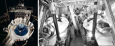 There was no blue film on the CM for the 125-hour test in September. 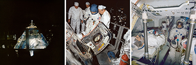 |
oly
Member Posts: 1436
From: Perth, Western Australia
Registered: Apr 2015
|
posted 10-06-2018 09:19 AM
Perhaps the later test included a test of the effectiveness of the reflective tape using the many thermal lamps inside the chamber? |
LM-12
Member Posts: 3723
From: Ontario, Canada
Registered: Oct 2010
|
posted 10-06-2018 09:29 AM
The June test related to the Apollo 7 mission in particular, and the September test related to the later lunar missions. From NASA:
Following completion of the June test, engineers modified the spacecraft while still in the chamber to a configuration to match that intended for future lunar flights. These modifications included replacing the older version side hatch with an easier to open unified lightweight version, installing a docking probe to the forward tunnel (which on lunar flights would be used to dock with the Lunar Module), and installing a high-gain steerable antenna (needed for communications at lunar distances). |
LM-12
Member Posts: 3723
From: Ontario, Canada
Registered: Oct 2010
|
posted 10-07-2018 03:32 PM
Some thermal modifications were made to the Skylab 2 command and service module after the Skylab 1 launch. Those modifications included adding reflective thermal tape (mentioned earlier) to parts of the CM heat shield. So that tape must have been applied to the Skylab 2 CM at the pad. From the "Skylab Mission Report - First Mission" on page 7-1: Following the loss of a solar array system wing on the Saturn Workshop during launch, steps were taken to minimize the spacecraft electrical power consumption by optimizing the command and service module thermal design for the first visit.Two thermal design modifications were made which conserved approximately 100 watts. One modification was the partial taping of the command module torroidal section to prevent excessive heat loss from the water tanks and reaction control system propellant tanks. This resulted in a heat loss rate approximately 1/2 that of the original. The other design change was to use the same tape to cover the electrical power system radiator panel 1, 5 and 25 percent of panel 4. |
LM-12
Member Posts: 3723
From: Ontario, Canada
Registered: Oct 2010
|
posted 10-13-2018 01:37 PM
Photo S69-32263 shows the Apollo 11 backup crew in the CM in the altitude chamber. Part of the blue protective film is peeled off below the hatch. The surface underneath does not look very mirror-like at all. Also note the area near window 4.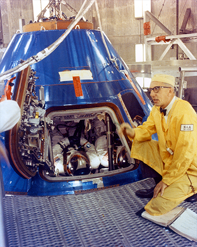 |
heng44
Member Posts: 3647
From: Netherlands
Registered: Nov 2001
|
posted 10-13-2018 02:37 PM
quote:
Originally posted by LM-12:
There was a blue film on the CM for the 177-hour test in June.
The photo of the June test you linked to is actually of a prior egress test. The blue film was removed for the 177-hour test.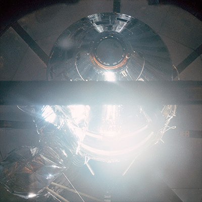 |
LM-12
Member Posts: 3723
From: Ontario, Canada
Registered: Oct 2010
|
posted 11-06-2018 12:29 PM
The Apollo 14 countdown chart has a "BPC INSTL" event from about T-59:30 hours to T-48:30 hours. The White Room was retracted to install the BPC.
|
oly
Member Posts: 1436
From: Perth, Western Australia
Registered: Apr 2015
|
posted 11-06-2018 07:17 PM
I am still searching for details of the BPC design and images of the cover prior to installation. I have studied the launch abort films available online to attempt to work out how the BPC separation occurred.The ability to remove and install the lower sections of the BPC lead me to believe that the lower segments deployed in a similar manner to what we see with payload fairings today, with the upper cone attached to the LES tower. |
LM-12
Member Posts: 3723
From: Ontario, Canada
Registered: Oct 2010
|
posted 11-06-2018 09:23 PM
The Apollo 11 LC-39 processing chart has a "CSM BPC FIT CK" event a few days after arriving at the pad.Regarding the jettison, wouldn't it be safer for the tower jettison motor to pull the tower and BPC away from the launch vehicle if the BPC stayed in one piece, as I always thought it did? |
oly
Member Posts: 1436
From: Perth, Western Australia
Registered: Apr 2015
|
posted 11-06-2018 11:34 PM
I also always understood that the BPC was a complete unit that separated in a single piece, as is found in models. One of the reasons I thought this was the fact that the BPC was designed to deflect the LES rocket plume from the CM windows.But images of the BPC lower sections segments removed while the spacecraft is on the pad, combined with the available descriptions and schematics do not show any method of fastening the sections together, or to the cone section, that appear to be structurally sound enough to withstand an assembled operation. The footage of the LES test appear to show pieces of the lower section of the BPC separate from the vehicle as the tower is pulled away, and the footage of the falling tower only shows the cone attached to the tower, not the complete BPC. This is what stemmed my earlier questions regarding the existence of a complete BPC and a request for any photos of such, or of an uninstalled or under construction BPC. Each cover was hand made and custom fit to each command module, due to the requirement for a good fit, and the variances in profile between each spacecraft. For this reason I presumed that the CSM at the Saturn V center at KSC may have the BPC on display, however this does not seem the case because the item on display at the Saturn V centre appears to be a mockup or boilerplate. Originally the BPC was only designed to be the smaller upper cone segment, however the later designs incorporated the lower sections. I may be off base with my suspicions, hence my research into this subject. |
LM-12
Member Posts: 3723
From: Ontario, Canada
Registered: Oct 2010
|
posted 11-07-2018 12:54 AM
How many aft BPC sections do you suppose there were? Eight?Compared to Apollo 14, the Apollo 9 countdown chart shows a much shorter BPC install event: from about T-50:30 hours to T-46:30 hours. |
oly
Member Posts: 1436
From: Perth, Western Australia
Registered: Apr 2015
|
posted 11-07-2018 01:57 AM
Page 41 of this document, which covers the block II spacecraft, shows a schematic of the BPC. There appears to be seam lines for five segments, not including the apex cover.The document has a diagram on page 144 showing the LES function with a complete BPC attached, but does not give any clear answer in the description. It may be that this was the simplest way of drawing this diagram. Figure 1-4 of the Block II Apollo Operations Handbook does not give any better detail. This is another reason I would like to see a complete cover. |
LM-12
Member Posts: 3723
From: Ontario, Canada
Registered: Oct 2010
|
posted 11-07-2018 09:35 AM
The BPC fit check shortly after arriving at the pad suggests to me that the aft BPC was not installed for the rollout from the VAB to the pad. |
oly
Member Posts: 1436
From: Perth, Western Australia
Registered: Apr 2015
|
posted 11-07-2018 08:48 PM
There is a list of items that are installed before launch including pyro, battery and consumables that require access to panels around the command module. By mapping the location of these items, and cross referencing your timelines, a relatively good picture may be established regarding which segments of the BPC would need to be removed.Chances are that the blue protective film was removed during the procedure to install each segment for the final planned time in an effort to reduce the surface degradation of the silver coating. Things of course do not always go to plan and some exceptions could be expected, together with changes due to revision of procedures and schedules. Would the MSS be required to access the rear of the command module? |
LM-12
Member Posts: 3723
From: Ontario, Canada
Registered: Oct 2010
|
posted 11-08-2018 05:00 AM
quote:
Originally posted by oly:
Would the MSS be required to access the rear of the command module?
I would say yes. I don't see how that area could have been accessed at the pad without the MSS platforms in place.The BPC segment at the CM hatch location must have been installed early on at the pad so the White Room could be moved into place. |
heng44
Member Posts: 3647
From: Netherlands
Registered: Nov 2001
|
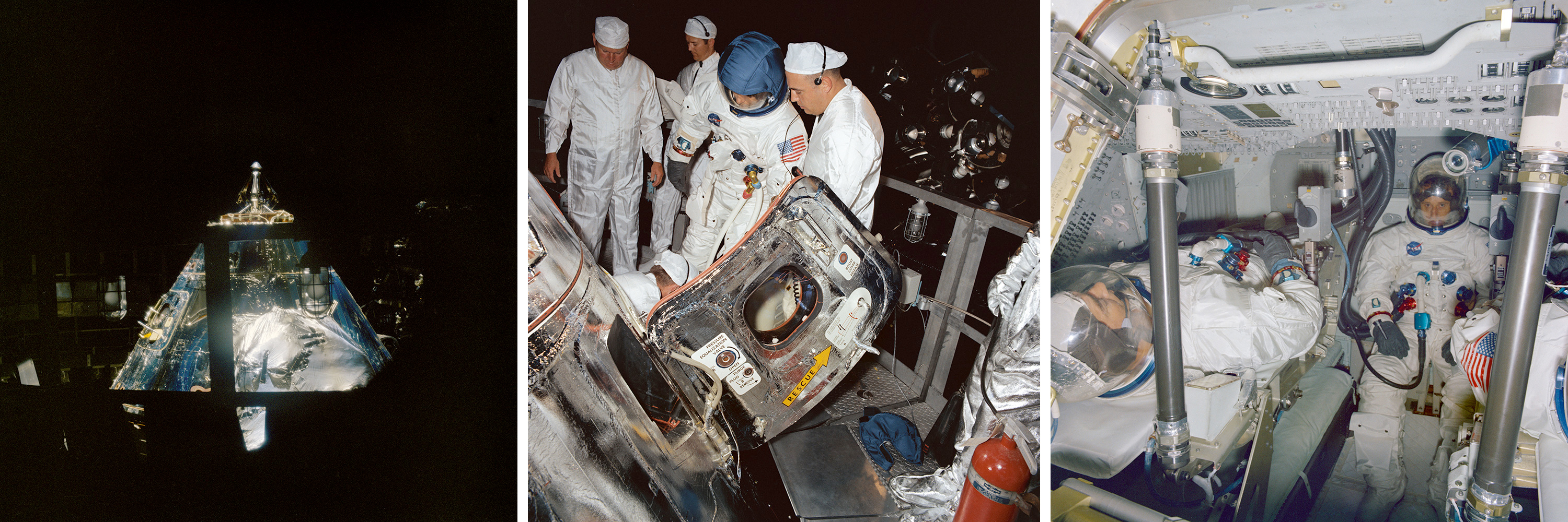
posted 11-08-2018 08:39 AM
I always assumed the LES plus BPC were installed together in the VAB before rollout. But apparently only the top portion of the BPC was installed, which explains why the spacecraft was always protected by a tarp during rollout. The lower segments of the BPC were installed for the CDDT and then removed again for servicing work. They were finally installed a few days before launch.The Apollo 14 photos below illustrate this. 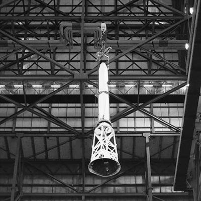 

|
LM-12
Member Posts: 3723
From: Ontario, Canada
Registered: Oct 2010
|
posted 11-08-2018 09:18 AM
quote:
Originally posted by heng44:
The lower segments of the BPC were installed for the CDDT
And, before that, the fit check mentioned earlier. |
LM-12
Member Posts: 3723
From: Ontario, Canada
Registered: Oct 2010
|
posted 11-08-2018 02:15 PM
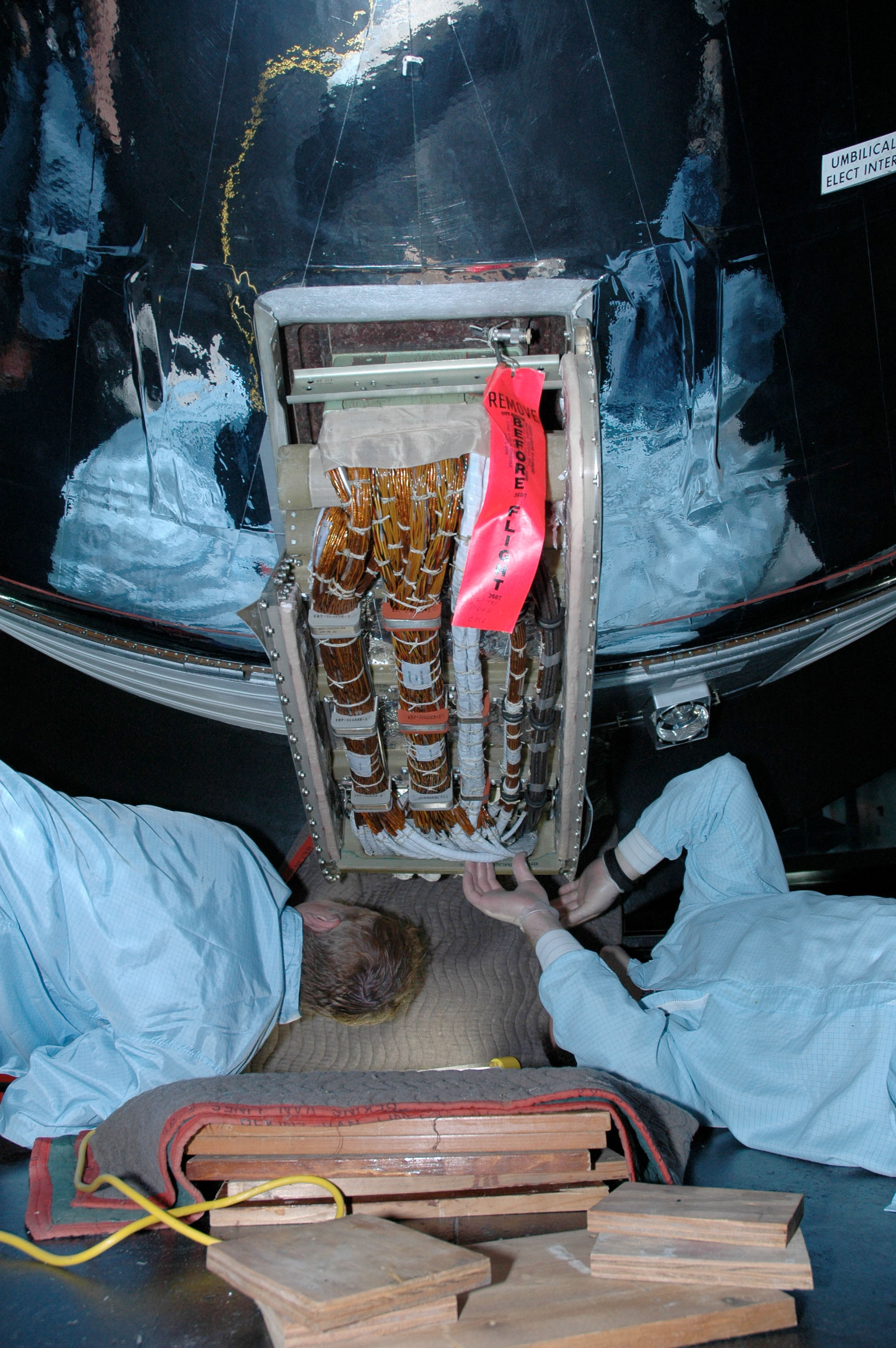
I wonder if any of the blue protective film (apart from the forward heat shield area) had been removed from the CM before Apollo 16 had to be rolled back to the VAB.The CSM was de-mated in the MSOB so that the command module aft heatshield could be removed. |


