|
|

|
|
Author
|
Topic: How did the Apollo FDAI/IMU work?
|
MattJL
Member Posts: 57
From: New Jersey, US
Registered: May 2012
|
 posted 10-12-2012 07:02 PM
  
After seeing this a while ago, I've been trying to understand how the Flight Director Attitude Indicator (FDAI) worked — mainly, the relationship between the inertial measurement unit (IMU) gimbals and the '8 ball.' I found this diagram but I'm at a loss to figure out how the position of the IMU was both detected and translated. Also, does anyone have any documentation on the FDAI/IMU? I have a few other questions about them, but I'm not certain on how to phrase them. |
DG27
Member Posts: 178
From: USA
Registered: Nov 2010
|
posted 10-14-2012 12:10 AM

Orientation of the IMU axes were detected using resolvers mounted on the IMU gimbal pivots. The outputs from the resolvers are used to drive servo motors in the FDAI. For example, using the diagram you referenced, the IMU Outer Gimbal Axis (OGA) resolver measures the angle of the outer gimbal relative to the vehicle structure. The IMU Outer Gimbal Axis is oriented along the spacecraft X Body axis (XB). The electrical output from the OGA resolver in the IMU is used to control a servo motor in the FDAI which rotates the FDAI Outer Gimbal. A resolver is also used on the FDAI outer gimbal axis (pivot) to measure the FDAI outer gimbal error and drive the error to zero by closing a feedback loop with the FDAI OGA servo drive motor. Thus the FDAI outer gimbal will accurately track, in real time, the position and movement of the IMU Outer Gimbal. Similar connections are used for the Middle Gimbal Axis and the Inner Gimbal Axis. This allows the FDAI to provide a visual representation of the position of the IMU stable platform relative to the spacecraft body axes. I don't have any documentation, but have a Block 1 FDAI unit and have been developing a wiring diagram for it. Hope this helps. |
MattJL
Member Posts: 57
From: New Jersey, US
Registered: May 2012
|
posted 10-16-2012 02:06 PM
Yes this has, thanks. |
David Carey
Member Posts: 802
From:
Registered: Mar 2009
|
posted 10-16-2012 03:10 PM
Great description.Here is a nice reference on the FDAI operations as a whole. The page contains images from John Fongheiser whose website contains other great pictures of his FDAIs opened up. Some of the servos and rotary contacts used in manipulating the eight-ball sphere are detailed. The LM10-14 Familiarization Manual also contains some details of IMU-FDAI signal sources/conversions/etc. These are wonderful instruments as noted in the earlier thread. I acquired an early Shuttle Sim FDAI from John which seems to have started out in the LM Sims. 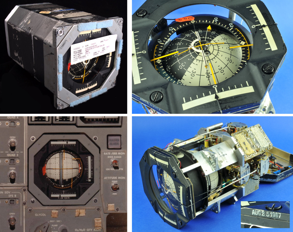 As seen in the upper right photo (click to enlarge), the Roll/Pitch/Yaw rate indicator needles surrounding the eight-ball have had their markings blacked out - just painted over really - but otherwise the details match exactly that of the LM FDAI as seen in the Apollo 14/LM8 Panel 2 photo lower left. The (Singer) Link labeling, 1967 manufacture date-stamp, and a few other tidbits are additional clues of re-use from Apollo/LM, I think. Most of the servos/resolvers of the eight-ball here are buried deep in the cage so hard to see. The galvanometers for the rate-indicator needles are the most prominent pieces of internal instrumentation. | |
Contact Us | The Source for Space History & Artifacts
Copyright 2020 collectSPACE.com All rights reserved.

Ultimate Bulletin Board 5.47a
|
|
|
 advertisement advertisement
|