|
|

|
|
Author
|
Topic: Apollo: Block I vs. Block II capsules
|
RichieB16
Member Posts: 582
From: Oregon
Registered: Feb 2003
|
 posted 05-01-2009 05:51 PM
   
So, I'm trying to understand some of the history behind the early Apollo program. It seems to me based on my reading and what I have been told here is that by the time Apollo 1 was nearing the launch it was clear that the Block I capsule wasn't a long term thing. It sounds like they just wanted to get a mission or two under their belt and then move to the Block II.My question is, was the Block I originally planned to be the final design or was there always a plan to have two Apollo capsule designs in the program. What is the point of building one spacecraft (Block I) if it was never really intended to be used. It seems that based on the hatch design, it wasn't EVA capable which would have made it pretty useless even early in Apollo. So, what was the purpose of the Block I design? |
mikej
Member Posts: 481
From: Germantown, WI USA
Registered: Jan 2004
|
posted 05-01-2009 08:06 PM
From very early on, NASA planned to have two types of Apollo command modules: Block I, used for Earth-orbital missions, and Block II, used for lunar missions (and the necessary testing missions in Earth orbit).The two-block approach was seen as a way to get hardware flying as soon as possible. NASA had decided on a "building block" approach to landing on the moon, with various mission types designated "A" through "G" (e.g., refer to Chariots for Apollo and then search for "Basic Missions"). These mission types included unmanned launch vehicle/spacecraft development missions and manned tests of the CSM in earth orbit. For these types of missions, docking-capable command modules were not required, and so a simpler design would suffice. Early on, there were plans to fly several manned Block I flights, but by the time the flight of Apollo 1 drew near, schedule pressures had whittled that down to two or even just one Block I mission. EVA wasn't a priority in the Block I missions. The Apollo spacesuits also came in Block I and Block II designs; the Apollo Block I suit was based on Project Gemini's non-EVA suit and was primarily intended for crew safety. Once NASA had the launch vehicle, spacecraft, and orbital operations worked out, they'd move on to the more complicated missions, with the more capable Block II spacecraft. |
Proponent
Member Posts: 59
From: London
Registered: Oct 2008
|
posted 05-02-2009 04:37 AM
To amplify mikej's reply, let my say that original design of the Apollo spacecraft pre-dates both the Gemini program and the lunar-landing goal. In this context, a Block I vehicle makes a lot of sense, for it would have been a huge leap from Mercury to a Block II-type spacecraft. It was originally expected that Block I would begin flying on the Saturn I in 1965. |
Jay Chladek
Member Posts: 2272
From: Bellevue, NE, USA
Registered: Aug 2007
|
posted 05-04-2009 03:28 PM
My understanding about the Block 1 and 2 craft was it wasn't something stipulated by NASA, but rather a North American Aviation innovation. When the contract was awarded for the Apollo spacecraft, many things had yet to be finalized and the changes were coming fast and furious in the early days. Several basic changes to the Apollo program's method of getting to the moon also changed at that time, such as going from Earth Orbit Rendezvous to Lunar Orbit Rendezvous (resulting in the LM contract and the need for a docking capability on the CM).As such, in late 1963, changes were still occurring on a daily basis and NAA needed to start building capsules for the first flight tests planned for 1965 and 66. It would take 18 months to build an Apollo CSM. As such, a baseline configuration was needed so the workers on the floor could begin manufacturing standardized parts for the first capsules. So the design was frozen as the block 1 while work continued on what became the block 2 capsules, which wouldn't be needed until late 1967/ early 68, meaning that design wouldn't need to be finalized until early to mid 1966 (after the first couple unmanned test flights had flown). It was known from early on that the Block 1 craft were too heavy to do a lunar flight (although there were some ideas drawn up to use a block 1 capsule for a Lunar flyby mission), but things didn't need to be refined as much for the test flights. Indeed as I understand it, since the Block 1 was such a dead end, some astronauts like Wally Schirra questioned the need for two manned test flights since the flight he was originally slated for was just a duplicate of Gus Grissom's mission. From NASA's standpoint though, they probably felt that enough stuff could be tested with the block 1 craft to get the early missions out of the way before the block 2 craft were ready. As it happened, even after the Apollo 1 fire, block one craft were used on the first two Saturn Vs to test out Block 2 hardware (essentially making them block 1.5s). |
E2M Lem Man
Member Posts: 846
From: Los Angeles CA. USA
Registered: Jan 2005
|
posted 05-06-2009 05:03 PM
Jay has it correctly. There was big plans to fly manned Block 1s and learn and improvise from them.But the missions came on slower than once planned for and the only Block 1s that were still planned in 1966 were Apollo 1 (Grissom) and Apollo 2 (Schirra) and when the Apollo 2 Service Module blew up in test, that flight was cancelled. |
sev8n
Member Posts: 236
From: Dallas TX USA
Registered: Jul 2012
|
posted 04-12-2018 07:18 PM
Reviving an old thread rather than starting a new one... I'm curious about the external configuration of the Block 1 Command Modules, and how and when (and if) it changed. Specifically, the location of the VHF scimitar antenna and the CM/SM umbilical connection. I recently visited the Fernbank Museum in Georgia to see the Apollo 6 Block 1 CM. Many Block 1 CM drawings show the two scimitar antenna at approx the +/-Z locations on the aft CM skirt. There were no scimitar antenna, or obvious mounting points, visible on the Apollo 6 CM. When did these antenna move from the CM to the SM, and were any Block 1 CMs ever constructed with said antenna? I have seen photos on the web that purport to be Block 1 CMs with the antenna but those seem to conflict with other photos and artifacts. I know the Block 1 CM/SM umbilical was near the aft hatch (-Z), and moved approx 180 degrees (to +Z) on the Block II with a larger and hinged cover. However on the Apollo 6 (CM-020) there is also an additional umbilical connection panel at the same +Z location as the Block II CM, and it shows obvious signs of having had a guillotine disconnect system similar to Block II. This connection point is also plainly visible on post-fire photos of the Apollo 1 (CM-012) capsule. Are there any photos or documentation showing the external umbilical connector design at this +Z connection point on the Block 1 CM? Did it feed through the BPC to the LES? |
mikej
Member Posts: 481
From: Germantown, WI USA
Registered: Jan 2004
|
posted 04-22-2018 04:48 PM
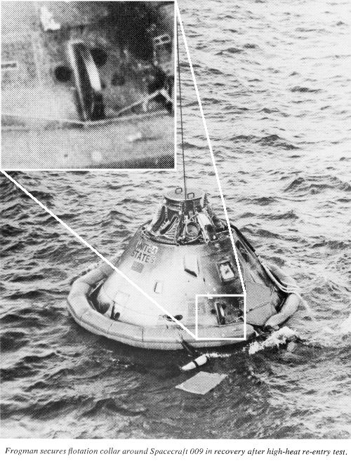
Apollo 4 and Apollo 6 both had simulated Block II umbilicals. I've got two photos of Apollo 4's umbilical on my website. NASA used the Apollo 6 simulated Block II umbilical to test ablator panels.Regarding the scimitar antennas: A fair amount of documentation referred to these as "SCIN antennas" (noting that "the word 'SCIN' is an acronym for 'SCImitar' and 'Notch'" for their construction). The antennas themselves were inside fiberglass housings. The SCIN antenna under the crew entry hatch was called the "surviving SCIN antenna" and the one opposite the hatch was called the "non-surviving SCIN antenna" (presumably because it was on the side to the spacecraft exposed to higher reentry heating and was expected to be destroyed during reentry, although see an AS-202 photo below). An undated Block I Apollo Spacecraft News Reference to which I had access (which was issued after Gemini 10 [18 July 1966] and apparently before AS-202 [25 August 1966]) has a diagram depicting the location of the two SCIN antennas but notes that they will be "relocated to SM for Block II." It does appear that most or all Block I command modules built before the Apollo 1 fire had the +Z and -Z SCIN antennas. S/C 002 (the first production Apollo spacecraft launched, on a Little Joe II, now residing at the Cradle of Aviation museum) is displayed with a SCIN antenna fairing under its hatch; the parachute prevented inspecting the back side of the spacecraft. However, a photo of the spacecraft being prepared for launch (photo at bottom right) shows the SCIN fairing. The Postlaunch Report for Apollo Mission A-004 (Spacecraft 002) has a diagram on page 5-99 (p. 166 in the PDF) depicting the antenna. Pages 5-174 and 5-183 (pp. 241 and 250 in the PDF) have low-quality photos showing the antenna fairing. S/C 008, which was used for thermal vacuum tests, has several photos with showing its SCIN antenna fairings (the fairing under the crew entry hatch has a protective covering over it in many of the photos): S/C 009, launched on AS-201, also had SCIN antennas. S66-20410 shows the +Z antenna's protuberance on the BPC (you'll need to click the photo to load the full-resolution version of the photo and then convince your browser to not shrink the photo to fit). There's also no Block II-style umbilical fairing. The News Reference I mentioned earlier has an AS-201 recovery photo showing the antenna fairing under the hatch:  S/C 011, launched on AS-202, also had SCIN antennas: - S66-50640 (red, at right)
- S66-50641 (visible under the three horizontal red dots in full-resolution version)
- S66-50642
- S66-50643 (again under the three red dots)
- S66-50644
- S66-49413 (not directly visible, but something at its location is causing the protective pad to deform and bulge
- S66-49247 (the charred remains of the "non-surviving" SCIN antenna are visible at right)
S/C 011 was displayed at Expo '67 in Montreal. Three photos show that the "surviving" SCIN antenna did, indeed survive (although more recent photos of it on A Field Guide to American Spacecraft show it without the antennas).The S/C 011 pre-launch photos above show that the +Z SCIN antenna is located where the Block II umbilical would be located, and so it has no simulated Block II umbilical. It would appear that S/C 012, Apollo 1, also had the antennas and lacked a simulated Block II umbilical. Apollo Operations Handbook: Command and Service Module (Spacecraft 012), dated 12 November 1966, has a diagram on p. 2.8-58 (p. 550 in the PDF) depicting the surviving and non-surviving SCIN antennas (the diagram also shows the notches in the scimitars). S67-15717 shows the SCIN antenna under the crew entry hatch. An unidentified spacecraft (which looks a lot like S/C 012 in the previous photo) shows the +Z SCIN fairing, again located where a Block II umbilical would be located. Page 2.9-29/2.9-30 (p. 609 in the PDF) of the S/C 012 Operations Handbook shows only a Block I umbilical guillotine (i.e., no guillotine for a Block II umbilical). It appears that the fire hastened the planned move of the scimitar antennas to the service module. The "Communications Subsystem Performance" section of the Apollo 4 Mission Report, on p. 5.13-2 (p. 275 in PDF), notes in that "The primary difference between Spacecraft 011 [AS-202] and Spacecraft 017 [Apollo 4] was in the antenna hardware configuration. Spacecraft 017 used four Block II S-band omnidirectional antennas flush mounted on the periphery of the aft heat shield and two Block II vhf/uhf scimitar antennas mounted on the service module." (The remaining photo links in this post are via the Apollo Archive Apollo Image Gallery, either "Early Apollo" or "Saturn V." The Apollo Archive doesn't allow one to link directly to a photo's metadata.) KSC-67P-208 claims to be a "top-to-bottom view of SA-501," but shows an atypical (in that it has no protective wrapping and has exaggerated panel lines) Block I type CSM with SCIN fairings. 67-HC-825, of Apollo 6, shows an Apollo spacecraft model in the background, which may be the spacecraft which was temporarily mated to SA-501. 67-HC-552 and KSC-67C-9604 are photos of Apollo 4 on the pad. If your browser shows you the full-sized photos, there will be no SCIN protuberances on the BPC and there will be no Block II umbilical fairing on the side of the spacecraft opposite the whiteroom (e.g., compare to KSC-71PC-69, of Apollo 14), but that there is a SCIN fairing on the service module. Recovery photo S67-49420 does not show a +Z SCIN fairing.
As with the AS-202 recovery photo above, a protective pad obscures the area under the hatch where the SCIN antenna would be, but unlike AS-202, Apollo 4 is not causing a bulge in the pad, indicating its lack of SCIN antenna. 68-HC-201 is an Apollo 6 launch photo. It's hard to tell whether or not there's a Block II style umbilical fairing just by looking at that photo, but it's obvious that there isn't one when comparing it to this Apollo 11 launch photo. The Apollo 6 photo also shows a SCIN antenna on the service module. Clicking the "banner" photo at the top of NASA's "50 Years Ago: The Second All-up Saturn 5 Test" page shows that the simulated Block II umbilical started off with all of its wires and tubing pre-severed and apparently painted over. (This would appear to be before the simulated wires were trimmed for the ablative panels.) Recovery photo S68-27161 shows no SCIN antenna under the hatch, and S68-27041 shows the lack of SCIN antenna near the simulated Block II umbilical. So, as far as I can determine, the Block I spacecraft, up to and including Apollo 1/Spacecraft 012, had the two scimitar/notch antennas on the command module and lacked simulated Block II umbilicals. The two Block I command modules launched after the fire (Apollo 4 and Apollo 6, S/C 017 and S/C 020) relocated the SCIN antennas to the service module and had simulated Block II umbilicals, although the umbilicals on these spacecraft were not actually connected to the service module and did not have Block II style umbilical fairings. Since we've been discussing Block I and Block II features and someone above called Apollo 4 and Apollo 6 "Block 1.5", I'll point out that Apollo 4 flew with a Block I crew entry hatch (although its hatch had a test panel with a simulated Block II thermal gap and seal mounted in place of the outer hatch's window) and that Apollo 6 flew the first "unified" (redesigned Block II) hatch. |
sev8n
Member Posts: 236
From: Dallas TX USA
Registered: Jul 2012
|
posted 05-19-2018 08:51 PM
mikej, thank you for that excellent and thorough response, much appreciated.Rather than consuming a lot of bandwith with embedded images, here is a link to an imgur folder of my Apollo 6 photos. In addition to closeups of the hatch area and the Block 1 style umbilical, there is also a photo of the simulated Block II umbilical connection. The museum staff was also very accommodating of my photography efforts. They removed the plexiglas cover over the hatch and allowed me to photograph the interior thru the hatch opening. One interior photo shows the cable routing to the Block 1 umbilical connector. imgur.com/a/rPfvS Enjoy... | |
Contact Us | The Source for Space History & Artifacts
Copyright 2020 collectSPACE.com All rights reserved.

Ultimate Bulletin Board 5.47a
|
|
|
 advertisement advertisement
|