|
Author
|
Topic: Apollo Lunar Module hatch hinge design
|
oly
Member Posts: 905
From: Perth, Western Australia
Registered: Apr 2015
|
 posted 09-17-2018 07:22 AM
   
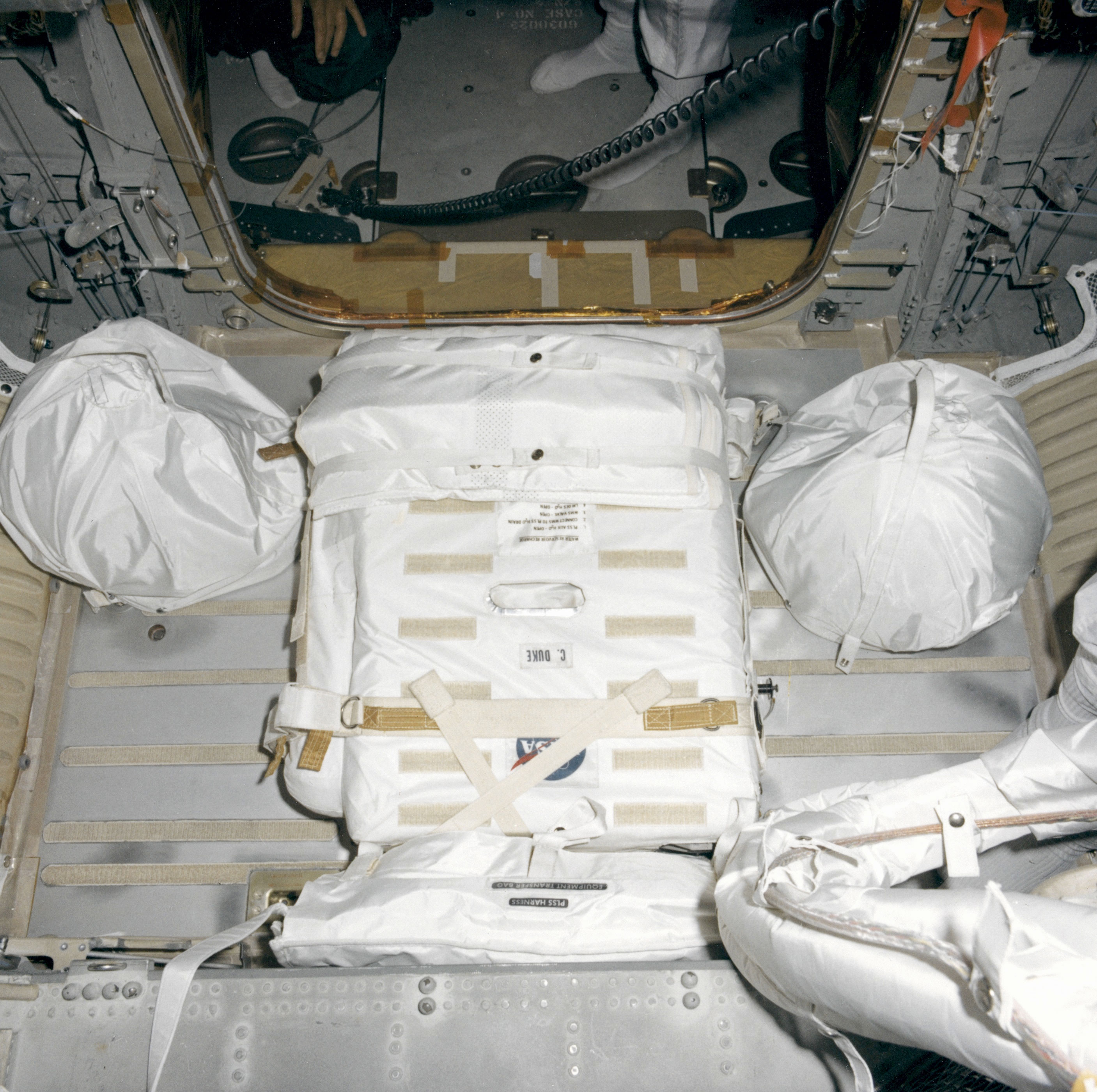
This photo of an Apollo lunar module closeout pre-launch shows a welded bracket installed within the door frame where the sealing surface is located. I believe that this bracket was used to protect the thin material of the door frame during servicing while the LM was installed within the LM adapter above the Saturn V. As can be seen in this photo, there was a PLSS backpack and the two LEVA fastened to the LM floor within the arc of the lower hatch swing. As the access via the top hatch was out of use due to the proximity of the service module engine exhaust nozzle, the lower hatch would have to be installed with these items already secured. I am curious how the ground crew installed the hatch, and how the hatch hinges were designed. Are these details available? Are there any photographs available of an uninstalled hatch inner surface, or of the inside of the LM with the catch closed that show detail of the hinges? 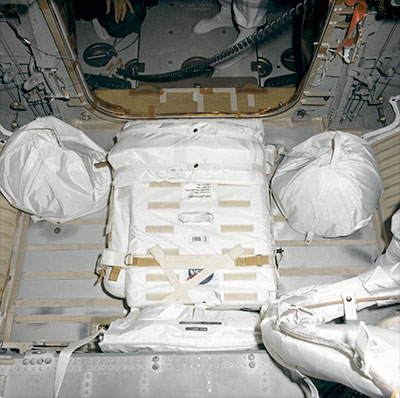 |
mf451
Member Posts: 61
From: NY, NY
Registered: Nov 2014
|
posted 09-17-2018 09:40 AM
I hope it's okay to piggyback a question I have as well: Can anyone explain what those pulleys are for on either side of the hatch? |
Jim Behling
Member Posts: 1463
From: Cape Canaveral, FL
Registered: Mar 2010
|
posted 09-17-2018 09:56 AM
quote:
Originally posted by mf451:
Can anyone explain what those pulleys are for on either side of the hatch?
Crew restraint system. It held the crew down in zero g. |
Headshot
Member Posts: 864
From: Vancouver, WA, USA
Registered: Feb 2012
|
posted 09-17-2018 01:51 PM
There were quick-release pins securing the hatch to its hinges on the LM. They were only accessible from the inside of the LM. Apogee Books' Virtual LM has some nice illustrations. |
Jim Behling
Member Posts: 1463
From: Cape Canaveral, FL
Registered: Mar 2010
|
posted 09-17-2018 02:16 PM
I don't think that was "the" final close out photo. The photographer would still have to get out of the LM. |
space1
Member Posts: 853
From: Danville, Ohio
Registered: Dec 2002
|
posted 09-17-2018 03:57 PM
I see oly's dilemma. If the hatch is installed from the inside, and the PLSS on the floor does not allow the hatch to swing open inside, how does the technician who has installed the hatch get out? |
oly
Member Posts: 905
From: Perth, Western Australia
Registered: Apr 2015
|
posted 09-17-2018 07:41 PM
Correct. This Apollo 17 closeout photo gives a better view of the restricted area left for the hatch to swing, or lack of area. quote:
Originally posted by Jim Behling:
I don't think that was "the" final close out photo. The photographer would still have to get out of the LM.
Here is a reverse angle photo showing a tech's feet inside the LM. This is from the Apollo 16 close out series of photos taken to record the security and location of everything on board and to record the switch positions. quote:
Originally posted by mf451:
Can anyone explain what those pulleys are for on either side of the hatch?
This photo shows the crew restraint system cables as stowed pre-launch. These were hooked onto the astronaut suit in the waist area to restrain the crew, acting like artificial gravity, so that the crew remained in position during zero-g. There was also Velcro positioned on the floor to give the crew something to grip their feet against so that their arms were free to move switches and levers. |
LM-12
Member Posts: 3207
From: Ontario, Canada
Registered: Oct 2010
|
posted 10-10-2018 11:56 AM
quote:
Originally posted by oly:
Are there any photographs available of an uninstalled hatch inner surface, or of the inside of the LM with the catch closed that show detail of the hinges?
Photo AS11-36-5399 shows the closed hatch and some details. |
space1
Member Posts: 853
From: Danville, Ohio
Registered: Dec 2002
|
posted 10-10-2018 12:44 PM
So obviously they could access the interior of the LM through the overhead hatch when the forward hatch was installed. |
LM-12
Member Posts: 3207
From: Ontario, Canada
Registered: Oct 2010
|
posted 10-10-2018 01:44 PM
Not at the pad. That last photo was taken during the mission.I think the LM forward hatch was (somehow) installed from the outside by someone on the SLA platform. The MSS platform would have been in place around the SLA. |
space1
Member Posts: 853
From: Danville, Ohio
Registered: Dec 2002
|
posted 10-10-2018 03:32 PM
Oops. Taken in flight. Thanks for pointing that out.I still can't think of any way the forward hatch could have been installed from outside the cabin. There are pins holding the hatch to the hinges. Unless there is a small access port that we don't know about, the pins would have to be inserted from inside the cabin. |
LM-12
Member Posts: 3207
From: Ontario, Canada
Registered: Oct 2010
|
posted 10-10-2018 09:00 PM
There is this view of the forward hatch of the LM cockpit on display at the Kennedy Space Center. Not sure if that display was an actual LM simulator. |
oly
Member Posts: 905
From: Perth, Western Australia
Registered: Apr 2015
|
posted 10-10-2018 11:09 PM
From an Apollo news reference, "Quick-release pins in the latch plate and hinges may be pulled from inside the LM to open the hatch in an emergency."This photo shows the hatch lower hinge, that looks to be some kind of parrot beak style mechanism, rather than a simple hinge half. This Virtual LM image does not show any specific detail that helps explain the hinge system, but does give a good overall concept. The multi-armed Buzz Aldrin composite image shows the lower hinge, but if not in focus. This image of the outside hatch area has something in the area of the lower hinge, that may be a hole in the insulation that allowed a cocking tool or access to hinge mounting hardware [maybe screws or bolts], or may be totally unrelated. This photo of the forward dump valve shows the upper hinge. |
Marc05A
Member Posts: 39
From: Reims, France
Registered: May 2009
|
posted 10-12-2018 02:07 PM
Dan Schaiewitz (former suit technician at Kennedy Space Center) might help you to answer this question. In his first post on cS, he explains how he delivered and stowed the astronaut suit life support equipment inside the LM the night before liftoff. Once inside the protective room that surrounded the Lunar Module, we removed the two portable life support systems (PLSS) and the emergency oxygen purge systems (OPS) from their protective containers. We then installed the hardware in their respective stowage locations. I had the distinction of crawling through the LM hatch into the LM to make the final verification of the PLSS controls and switches. |
oly
Member Posts: 905
From: Perth, Western Australia
Registered: Apr 2015
|
posted 10-12-2018 07:55 PM
If Dan is reading this hope he can shed some light on this subject. As can be seen in the first photo of this post, the PLSS backpacks have already been installed when the close out photo was taken (which were taken to record the position of switches and the location/security of items after people had finished working within the LM).
|
schnappsicle
Member Posts: 396
From: Houston, TX, USA
Registered: Jan 2012
|
posted 10-19-2018 09:09 AM
Photo AS11-36-5399 mentioned above shows a blue "Lunar Contact" indicator. Is that the one that indicated they needed to shut down the engine? For some reason, I always thought it was a red light. |
oly
Member Posts: 905
From: Perth, Western Australia
Registered: Apr 2015
|
posted 10-19-2018 09:21 AM
Yes, that is the famous Contact Light.This image shows what the illuminated light looks like. |
LM-12
Member Posts: 3207
From: Ontario, Canada
Registered: Oct 2010
|
posted 10-19-2018 02:44 PM
The other blue "Lunar Contact" light is on Panel 1 and higher up, near eye-level. It can be seen in photo KSC-69P-814. |
SpaceAholic
Member Posts: 4437
From: Sierra Vista, Arizona
Registered: Nov 1999
|
posted 10-19-2018 09:46 PM
quote:
Originally posted by oly:
Yes, that is the famous Contact Light.This image shows what the illuminated light looks like.
And its getting close to re-illumination ..plan is to do so again on the AP11 50th during a commemorative event hosted by the University of Arizona Lunar and Planetary Lab
|
oly
Member Posts: 905
From: Perth, Western Australia
Registered: Apr 2015
|
posted 10-19-2018 10:06 PM
Fantastic, I think it is a brilliant idea to keep such information alive and out there, this is awesome work. There are so many questions that can be answered doing such things. What shade of blue is the light, what sounds do these panels make {if any) when powered up, what sounds do the switches make etc. Sharing such information helps todays generation make simulators and movies that can accurately show what it was like. I hope you can capture this kind of information and share it for future use.
|
Daniel on the Moon
Member Posts: 354
From: Bronxville, NY
Registered: Jun 2015
|
posted 10-19-2018 10:24 PM
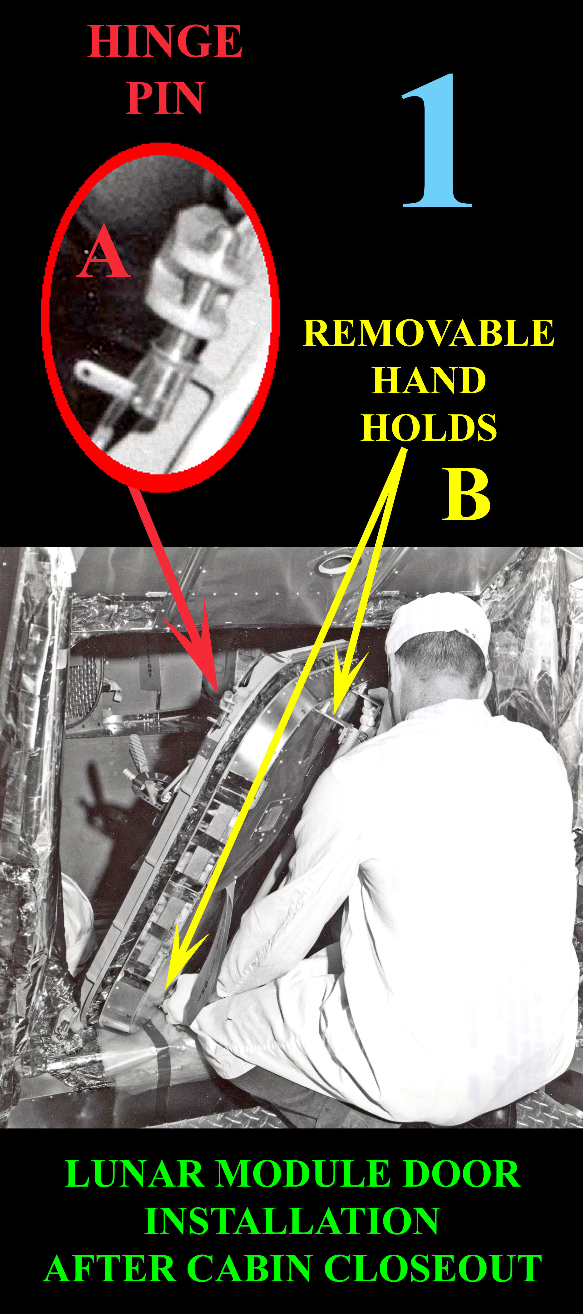
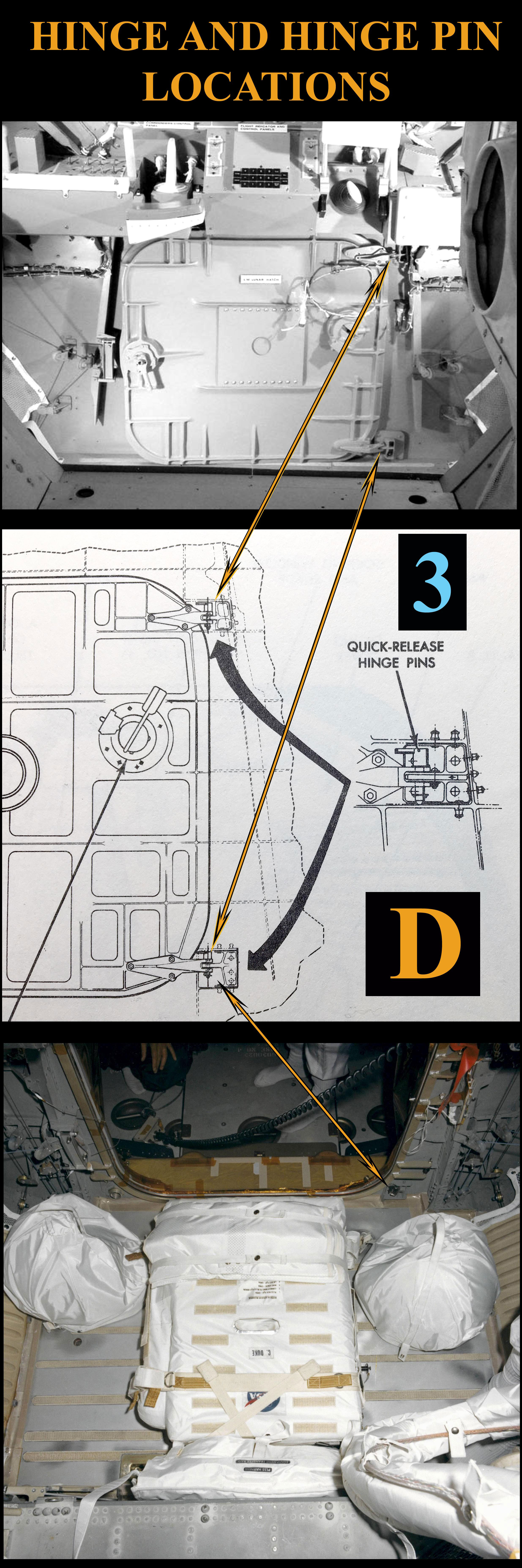
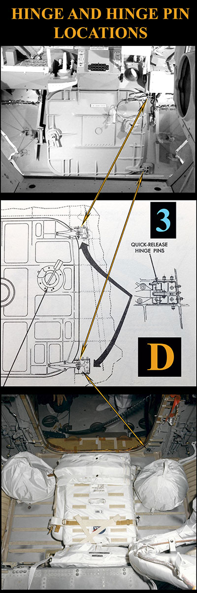
The Forward Hatch was installed from the outside of the LM cabin. Referring to the first graphic, a technician is maneuvering the LM Hatch Door using attachable/removable Handholds B. Despite a minimal 5.4" clearance between the PLSS and hatch opening (graphic 2), the technician is able to position the hatch door female hinges into the mating bulkhead upper and lower mating male hinge receptacles.With just enough space available to position his hand in close enough proximity to the mated male/female hinge components D, the technician is able to insert Quick-Release Hinge Pins A (graphic 1) to secure the hatch door to the bulkhead (graphic 3). With the hinge pins inserted, the technician closes and secures the hatch door and removes the hand holds.  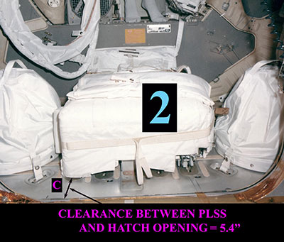
|
oly
Member Posts: 905
From: Perth, Western Australia
Registered: Apr 2015
|
posted 10-20-2018 01:46 AM
Daniel, thank you so much for you description and images that explain a detail I have been seeking an answer to for many years. The information that you have provided within these forum pages is incredible, and the details that you can provide are things that should be preserved and shared for generations to come. Specific engineering details such as this are what fascinate me about the Mercury, Gemini and Apollo era, It would be amazing to learn half of what you know. Again thank you for providing this information. |
space1
Member Posts: 853
From: Danville, Ohio
Registered: Dec 2002
|
posted 10-20-2018 06:08 AM
Daniel, we are most grateful for your information. I wouldn't have thought that there would be enough room to insert the hinge pins from the outside. But the designers made provisions for that. Thanks again for your input. |