|
Author
|
Topic: Apollo hardware reference by contract, part nos.
|
bklyn55
Member Posts: 390
From: Milford, CT
Registered: Dec 2014
|
 posted 08-30-2015 10:05 AM
   
Does anybody know of a reference document (or documents), or a website, where you can look-up the details of a specific piece of Apollo hardware given the contract and part number? |
bklyn55
Member Posts: 390
From: Milford, CT
Registered: Dec 2014
|
posted 08-30-2015 11:49 AM
To be more specific; Apollo includes Saturn, C/S modules, and LM. By part, I include down to valve and filter level, either flight or GSE. |
nasamad
Member Posts: 2181
From: Essex, UK
Registered: Jul 2001
|
posted 08-30-2015 01:05 PM
I don't think there will ever be any such site or list, given the number of vehicles built at a guess I'd say your looking in excess of 10 million components if we were to believe the often quoted figures for Apollo/Saturn vehicles. |
Jim Behling
Member Posts: 1702
From: Cape Canaveral, FL
Registered: Mar 2010
|
posted 08-30-2015 05:37 PM
quote:
Originally posted by bklyn55:
Does anybody know of a reference document (or documents), or a website, where you can look-up the details of a specific piece of Apollo hardware given the contract and part number?
That would be the drawing system for the whole vehicle. The equivalent for the shuttle or other vehicles in the past or current don't exist online. |
MadSci
Member Posts: 243
From: Maryland, USA
Registered: Oct 2008
|
posted 09-02-2015 03:52 AM
A good start would be to search all these forums for posts by a member name: Spaceaholic.Scott is one of the most knowledgeable people regarding identifying hardware, and while he has never really compiled his knowledge of serial/part numbers he has answered a lot of specific questions, often imparting his experience regarding the meaning of many Part numbers and how they can be traced to specific vehicles, programs etc. Sadly, I think that no one knows Al lithe part numbers and their meanings. Remember, this was the 50s to the early 70s. There were no computers on peoples desks, no interconnections that were not specifically designed for particular machines, and at the end of the programs, Congress ordered it all to be sold as scrap. Given the brevity of the programs, there was no one tasked with documenting all the information in the way it would be done today. The documentation and quality systems were ahead of their times but wouldn't pass muster today. If YOU ever find anything resembling their Holy Grail, please do share it with everyone! |
Kizzi
Member Posts: 36
From: Manchester, England
Registered: Apr 2012
|
posted 09-05-2015 07:14 AM
This may not help with your quest, but it's interesting background nonetheless.I came across JSC Policy Reference (JPR) 8500.4, which defines the part numbering convention as: Position 1. Letter 'S' designates the NASA center.Position 2.
A Arrangement Drawing
B Master Plan Drawing
C Construction Drawing
D Detailed Assembly Drawing
E Assembly Drawing
F Erection Drawing
G Installation Drawing
H Wiring Harness Drawing
I Diagram Drawing
J Kit Drawing
K Book Form Drawing
L Envelope Drawings Position 3.
A Gemini
B Apollo
C Skylab A and B (formerly Apollo Applications Program)
D Space Shuttle
E Earth Resources
F Apollo-Soyuz Test Program
G Space Station Program
H Constellation Program
K X-Crew Return Vehicle
M Russian-Mir Program
N New Initiatives or Advanced Programs
W Institutional Programs
Y Developmental (non-program oriented)
Z Multiprogram applications Of course, during Apollo, "B" didn't mean Apollo, but the Department responsible, e.g. B = Crew Systems
D = Space Physics Positions 4 and 5
11 Environmental System
12 Crew Personnel Equipment
13 Space Suits
14 Waste System
15 Development Flight Instrumentation.
16 Operational Instrumentation/Communication
17 Field Testing Instrumentation
18 Scientific Instrumentation Communication
19 Stabilization and Control System
20 Guidance and Navigation Control System
21 Abort Guidance System
22 Solid Propellant Motors
23 Liquid Propulsion Systems
24 Reaction Control Systems
25 Power Generators
26 Pyrotechnics
27 Spacecraft Structures
28 Heat Protection
29 Mechanical Systems
30 Earth Landing
31 Planetary Landing
32 Crew Station
33 Crew Operation Equipment
34 Recovery Support Equipment
35 (Inactive)
36 Developmental, Experimental Eq. and Test Facilities
37 Spacecraft Models (Wind Tunnel/Free Flight)
39 Experimental Equipment (Flight)
38 Ground Support Equipment
40 Survival Equipment
41 Operating Logic Schematics
42 Bio-instrumentation
43 Crew Trainers and Simulators
44 Concept Design Category
45 Spacecraft Operational Profile
46 Life Sciences Experiments
47 Scanning Sensing Systems
48 Food Systems
50 Classified Drawings (of any equipment)
51 X-38 Crew Return Vehicle
52 Bio-Medical Equipment Drawing Sequence number, so for SEB12100030 it would be 100030 Dash numbers
Numbers -001 to -099, -101 to -199, and -201 to -299 are reserved for individual components or detailed parts on detail drawings. Other ranges have different specialist meanings. I always considered the NASA inventory management system, invented for Apollo, were a contributing factor in the successful safety record. Even more, the management techniques developed where one of the the positive off-shoots of the moon landing program. |
Jim Behling
Member Posts: 1702
From: Cape Canaveral, FL
Registered: Mar 2010
|
posted 09-05-2015 09:56 AM
quote:
Originally posted by Kizzi:
I always considered the NASA inventory management system, invented for Apollo, were a contributing factor in the successful safety record. Even more, the management techniques developed where one of the the positive off-shoots of the moon landing program.
That is a drawing system and not an "inventory management system." It was not invented for Apollo nor by NASA. It is a standard process of any successful aerospace contractor and it predates NASA. Also, the management techniques predate Apollo (see Polaris and ICBM programs).Back to the drawing system, which is JSC's and is for any produced on center. It would mostly be found associated with crew equipment and experiments. Hardware produced by the spacecraft and launch vehicle contractors would be under each contractor's drawing system. |
Kizzi
Member Posts: 36
From: Manchester, England
Registered: Apr 2012
|
posted 09-07-2015 04:17 PM
Thanks for setting straight on drawings, and hardware.I seem to have got my management terms a little mixed. What I half remembered, and just found, was this quote: In terms of numbers of dollars or of men, NASA has not been our largest national undertaking, but in terms of complexity, rate of growth, and technological sophistication it has been unique... It may turn out that [the space program's] most valuable spin-off of all will be human rather than technological: better knowledge of how to plan, coordinate, and monitor the multitudinous and varied activities of the organizations required to accomplish great social undertakings. From the Program Management Concept in "Project Apollo: A Retrospective Analysis." |
bklyn55
Member Posts: 390
From: Milford, CT
Registered: Dec 2014
|
posted 09-07-2015 09:30 PM
I realize that identifying every component is a difficult and time consuming effort. What I was looking for is a generalized system whereby one can identify an Apollo program component as to craft, system, and maybe sub-system by a specific letter/number. For example; a fuel filter in the RCS of the command module is identified as a part with P/N ABC123-00, where A means the CM, B means the RCS system, C stands for fuel filters, and the numbers represent a specific part. |
SpaceAholic
Member Posts: 5004
From: Sierra Vista, Arizona
Registered: Nov 1999
|
posted 09-07-2015 11:23 PM
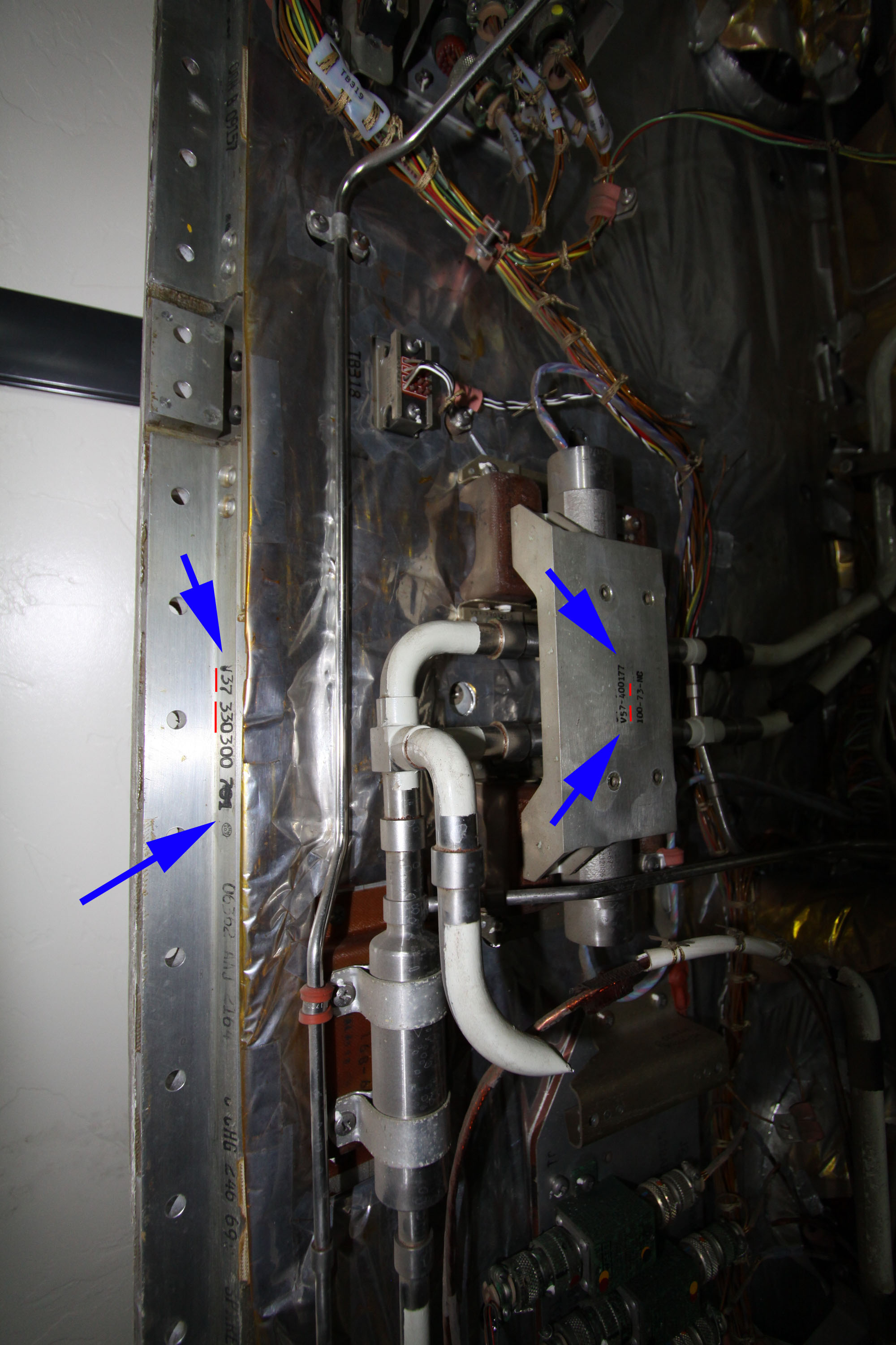
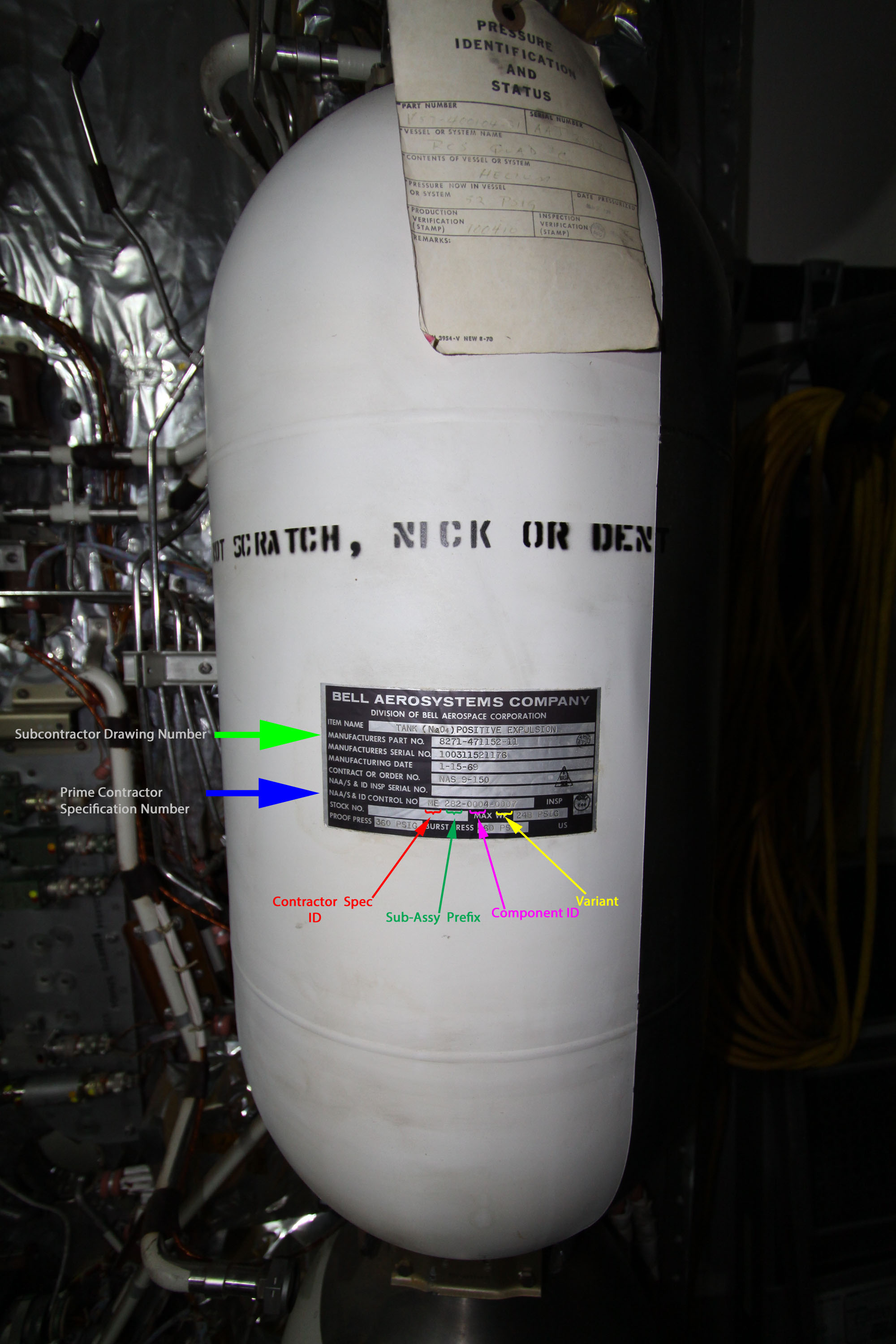
Good luck with that... as mentioned previously in the thread, there was not standardization in drawing numbers between contractors.An example of the disparity, illustrated as part of a Service Module RCS Quad panel. North American Rockwell "V" prefix components number in image 2 (parts produced "in house"); propellant tank label zoom-in showing disparate (Bell Aerospace) subcontractor drawing/specification number structure. There is a proprietary logic to drawing systems within individual contractors, but not across the field. 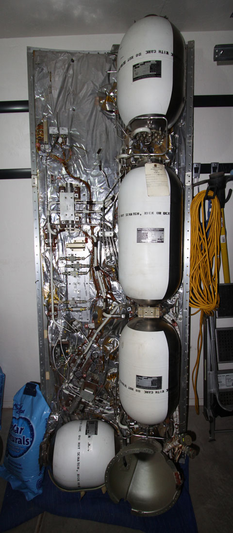 

|
Jim Behling
Member Posts: 1702
From: Cape Canaveral, FL
Registered: Mar 2010
|
posted 09-08-2015 06:29 AM
quote:
Originally posted by bklyn55:
What I was looking for is a generalized system whereby one can identify an Apollo program component as to craft, system, and maybe sub-system by a specific letter/number.
Drawings systems don't work that way. That doesn't even exist within the drawing system of one contractor. In the second photo above, the prefix of V57 on the bracket might be just a drawing with many brackets associated with the RCS or it could be specific to that one assembly. And the V37 prefix could be a specific panel for the RCS or it could be one of many of the SM panels.Also, drawings just don't manufacture end items. There are also assembly drawings, installation drawings, process drawings, etc. Designer starts working on a piece of hardware, the first thing he does is that he goes to the company's document/drawing center and requests a drawing number. Within a project, the numbers are assigned sequentially. So two sequential part numbers may be from the same project but be the furthest away from each other on the end item. Just a hypothetical example, the hold down bracket on the base of the S-IC and the LOX vent on the top of the stage. Assembly and installation drawings take the hodge podge of piece parts and put them into subsystems and primary systems. Which then in turn more Assembly and installation drawings turn into a finished end item. So in summary, part numbers by themselves are not readily intuitive or descriptive. One needs the actual drawing or part tag to learn more. |
SpaceAholic
Member Posts: 5004
From: Sierra Vista, Arizona
Registered: Nov 1999
|
posted 09-08-2015 11:24 AM
With respect to Project Apollo, V37 and V57 constitute drawing prefixes for the Service Module. This late example of the the Quad RCS assembly (remnant from ASTP) leverages components from two generations of panels. |
Jim Behling
Member Posts: 1702
From: Cape Canaveral, FL
Registered: Mar 2010
|
posted 09-08-2015 11:43 AM
Just some info. Part numbers consist of a drawing number and a dash number. A single drawing can involve the design of many parts.
|
space1
Member Posts: 905
From: Danville, Ohio
Registered: Dec 2002
|
posted 09-08-2015 05:52 PM
I have found that most of the drawings for Mercury/Gemini (McDonnell) and Apollo/Shuttle (Rockwell) do follow a general pattern. All V36 drawings are Apollo Command Module (CM), V37 are Service Module (SM), V56 are CM for Apollo Applications specific parts (Skylab and ASTP), V57 are SM for Apollo Applications. VO70 is shuttle Orbiter. For example, on this site is a reference to tile locations by part number, showing a logical pattern. |
SpaceAholic
Member Posts: 5004
From: Sierra Vista, Arizona
Registered: Nov 1999
|
posted 09-08-2015 05:57 PM
V070 is the most prolific shuttle drawing prefix, other less common include (V)602, 646 and 733  |
space1
Member Posts: 905
From: Danville, Ohio
Registered: Dec 2002
|
posted 09-08-2015 08:03 PM
For clarity we should note that the Orbiter numbers begin with "Vee Oh Seven Zero" (VO70) not "Vee Zero Seven Zero." This may be an abbreviation for Vehicle Orbiter, as there are VT70 numbers which are known to be "T"est parts. |
Jim Behling
Member Posts: 1702
From: Cape Canaveral, FL
Registered: Mar 2010
|
posted 09-08-2015 09:47 PM
quote:
Originally posted by space1:
I have found that most of the drawings for Mercury/Gemini (McDonnell) and Apollo/Shuttle (Rockwell) do follow a general pattern...
How is Mercury/Gemini (McDonnell) part of that pattern? |
SpaceAholic
Member Posts: 5004
From: Sierra Vista, Arizona
Registered: Nov 1999
|
posted 09-08-2015 10:24 PM
John obviously included Mercury and Gemini as part of the broader discussion and I am sure didn't suggest they were part of the NAR drawing system. Common knowledge those programs fall under 45- and 52- specifications respectively. |
space1
Member Posts: 905
From: Danville, Ohio
Registered: Dec 2002
|
posted 09-09-2015 04:59 AM
Scott is right. I meant that the McDonnell drawing system also followed a logical pattern, unrelated to the Rockwell system.This is in contrast to some systems with which I am familiar. For example the system used by GTE, which produced the wireless intercom system for shuttle, uses the highest level digits to designate the type of drawing, not the program. Drawings beginning with "02-" are assembly drawings. You could have an assembly drawing for a lab bench right after an assembly drawing for a satellite antenna. The detailed drawings were allocated in a group based on how many were thought to be needed. If any more were needed they would be in a different group of numbers. To find the drawings for anything in such a system you need the assembly drawings. |
Jim Behling
Member Posts: 1702
From: Cape Canaveral, FL
Registered: Mar 2010
|
posted 09-09-2015 08:55 AM
quote:
Originally posted by space1:
I meant that the McDonnell drawing system also followed a logical pattern, unrelated to the Rockwell system.
However, the "logic" ends after the initial project assignment to a range of numbers. Usually, the drawing numbers are then assigned sequentially as they are requested. |
SpaceAholic
Member Posts: 5004
From: Sierra Vista, Arizona
Registered: Nov 1999
|
posted 09-09-2015 09:16 AM
Not quite true (for the CSM at least).For example, NAR drawing numbers convey proximate component location within the flight vehicle if one understands how to interpret them. |