|
Author
|
Topic: Block II Command Module electronics
|
SpaceAholic
Member Posts: 4437
From: Sierra Vista, Arizona
Registered: Nov 1999
|
 posted 11-28-2009 07:36 PM
   
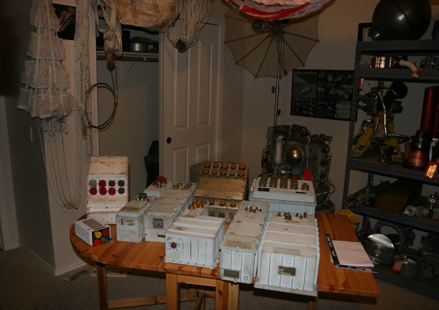
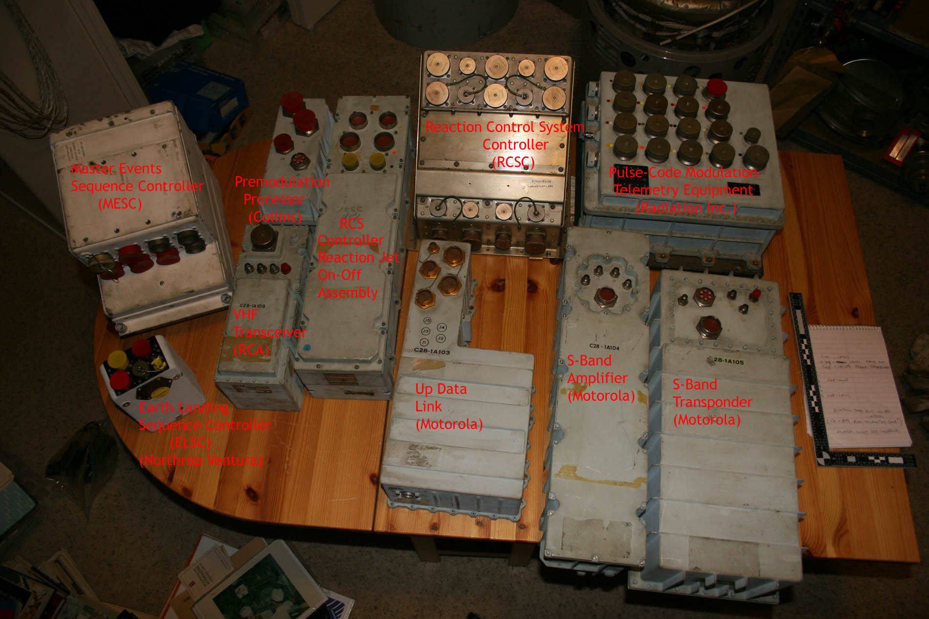
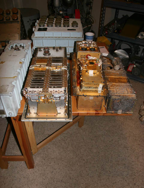
Some Block II Apollo Command Module electronics assemblies added to the collection. The seemly nondescript boxes house quite elaborate technology. More notable assemblies here: Master Events Sequential Controller (white assembly top left), Earth Landing Sequence Controller (bottom left) and to the bottom right the S-Band TWT (amplifier) and CM S-Band Transponder, and a PCM Multiplexer (top right).  
|
SpaceAholic
Member Posts: 4437
From: Sierra Vista, Arizona
Registered: Nov 1999
|
posted 11-28-2009 07:36 PM
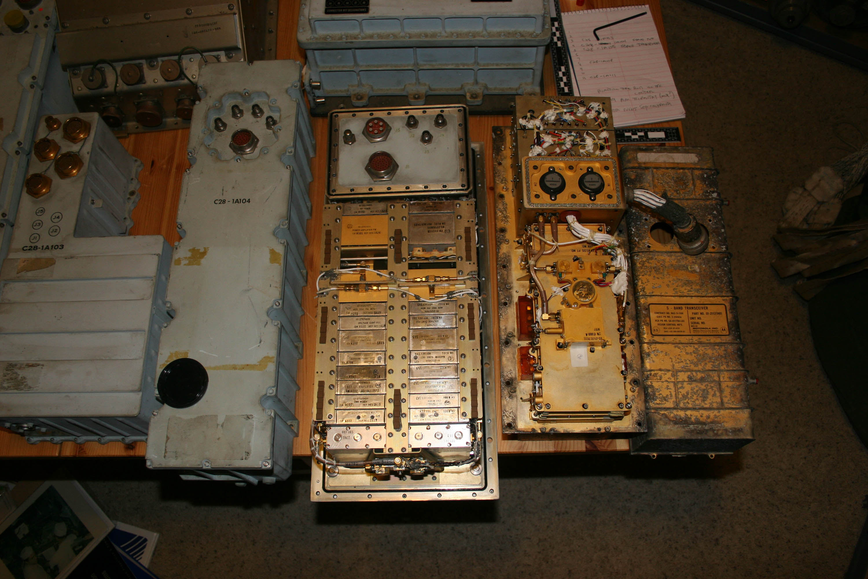
Here (likely for the first time in 40 years), have removed the cover of the Command Module S-Band Transponder and imaged concurrently with the Lunar Module S-Band Transceiver (discussed previously in an earlier thread). These artifacts, as well as the affiliated CM S-Band TWT (amplifier) to the left in the first image were manufactured by Motorola. Both the radios, which along with the LRV LCRU during J-Missions, comprised the Unified S-Band (USB) system enabled the only deep space connectivity available for passing voice, TV, data, telemetry between the spacecraft and JSC. 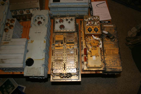 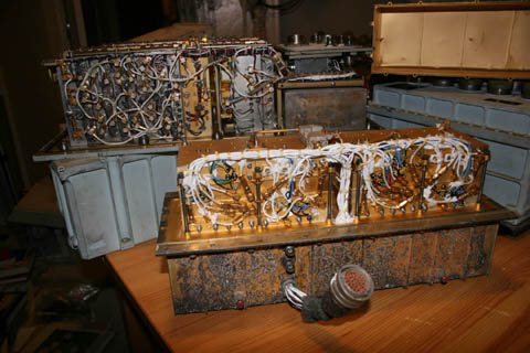
|
Jurg Bolli
Member Posts: 977
From: Albuquerque, NM
Registered: Nov 2000
|
posted 11-29-2009 12:56 PM
This type of shopping appeals to me! Great find. |
SpaceAholic
Member Posts: 4437
From: Sierra Vista, Arizona
Registered: Nov 1999
|
posted 11-29-2009 01:49 PM
Thanks... though I dont get credit for actually "finding" these, they were obtained from another collector who along with a very few others had the vision to gather this material from the prime contractors at wind-down of the program(s) in the mid 70's. Had it not been for these core, first generation space hardware collectors most of the Mercury, Gemini and Apollo artifacts in private circulation would have certainly been destroyed (the activities of these early collectors represent a significant bit of history in itself). It's my assessment that at least 90 percent of the hardware can be traced back to this group. We owe a huge debt of gratitude to folks who by choice elect to remain off the radar — they are truly the unsung heroes of the hobby. I have updated one of the photos above with the functional IDs of the components (click on the second image (first posting) above to read them). |
SpaceAholic
Member Posts: 4437
From: Sierra Vista, Arizona
Registered: Nov 1999
|
posted 12-02-2009 12:37 AM
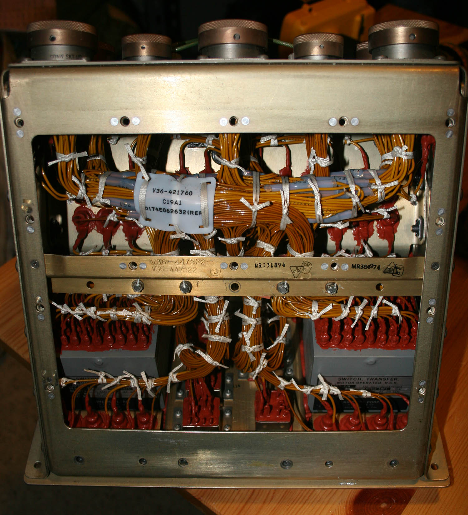
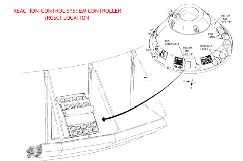
Here's an internal peek within the Command Module RCS Controller and location for context on the Command Module. Post Apollo 1 fireproof (red) potting can be seen; also visible at the bottom left/right corners, the redundant motor operated transfer switches responsible for shifting reaction system control from the Service Module to the Command Module RCS at separation. 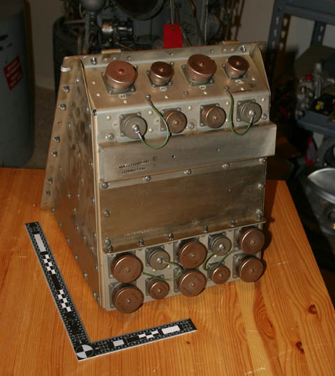
|
DMScott
Member Posts: 354
From: Lexington, MA, USA
Registered: Dec 2005
|
posted 12-02-2009 03:12 AM
Scott, congratulations on another spectacular find. There are enough doodads in those items to keep you occupied for months. |
space1
Member Posts: 853
From: Danville, Ohio
Registered: Dec 2002
|
posted 12-02-2009 05:21 AM
Scott, you are right about the efforts of the early space collectors in preserving these artifacts. They succeeded in saving items that others would have scrapped.You noted that the red potting on the wires was fireproof and post-Apollo 1. The red potting is high temperature RTV (room temperature vulcanizing) rubber. It's use pre-dates Apollo 1. The fireproof coating applied after Apollo 1 is Ladicote, a green spongy material. It was applied over the RTV potting. On my web site, you can see examples of a Block I panel with the RTV, and a Block II unit with the Ladicote. But I don't think the RTV in fully enclosed units such as this was coated with Ladicote after the Apollo fire. Beautiful units! (That reminds me of a Far Side comic (paraphrasing): "An anthropologist's dream - a pretty woman in one hand, and the skull of Aristopheleus in the other." I can so relate!) |
SpaceAholic
Member Posts: 4437
From: Sierra Vista, Arizona
Registered: Nov 1999
|
posted 12-02-2009 08:44 AM
Acknowledged John... all the units with the exception of the S-Band Transponder have production/acceptance dates of 1968 or later Block II CSM and its probable one or more have flown history. The S-Band Transponder has a late modification which enabled High Gain antenna acquisition (this mod was done also in 68 and was the last enhancement NASA directed Motorola to provide to the radio) so I know that it is a flight ready variant as well. Thanks for the correction on the RTV vs Ladicote. |
SpaceAholic
Member Posts: 4437
From: Sierra Vista, Arizona
Registered: Nov 1999
|
posted 12-02-2009 11:30 PM
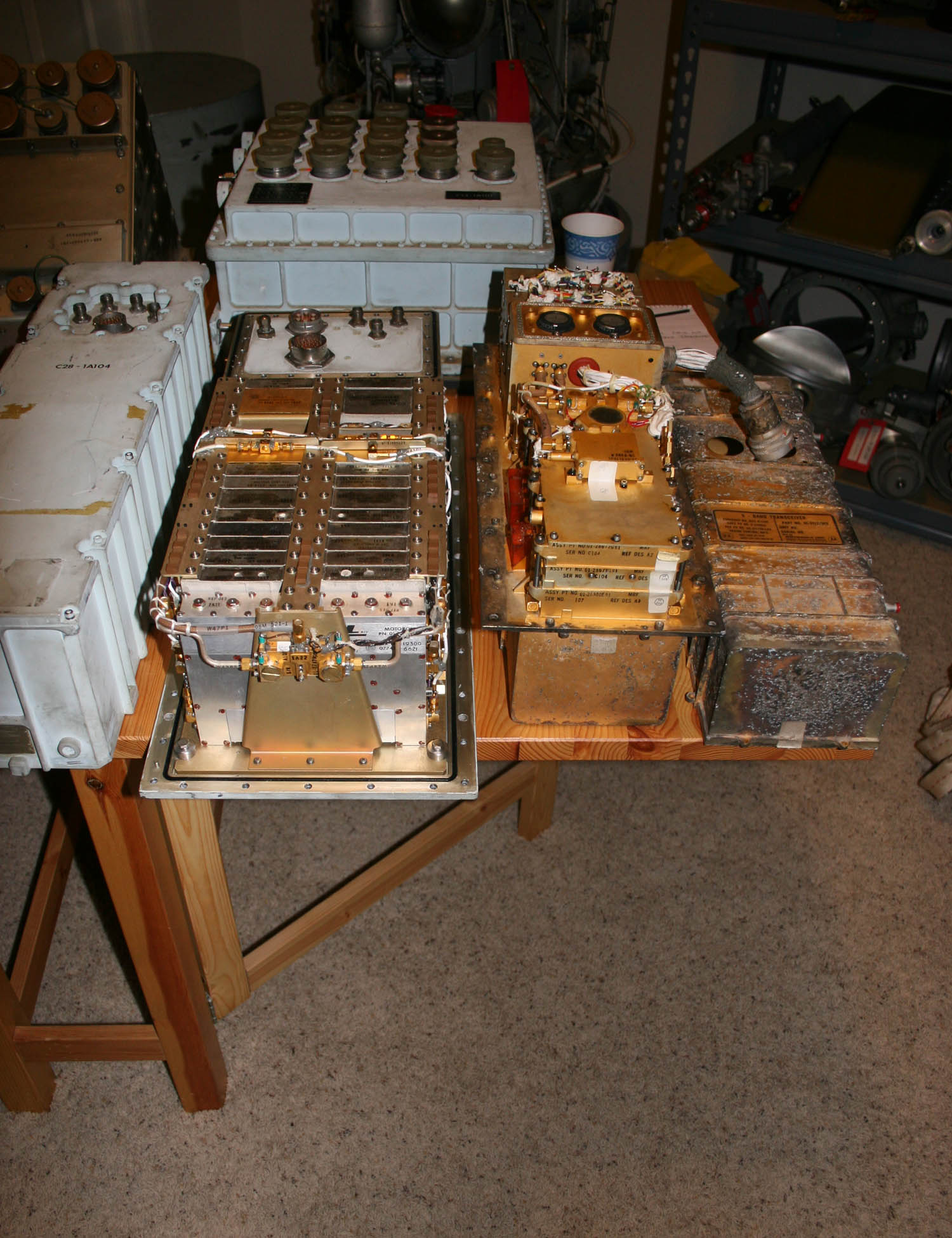
Internal image of the fully redundant Command Module S-Band Amplifier (output was routed to the High Gain and Omni-Directional antenna's on the CSM). S-Band Transponder to the left.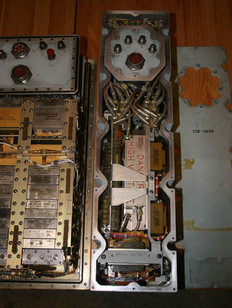 |
SpaceAholic
Member Posts: 4437
From: Sierra Vista, Arizona
Registered: Nov 1999
|
posted 12-12-2009 08:32 PM
Internal of the Command Module Very High Frequency (VHF) Transmitter/Receiver (like the Unified S-Band Transponder its architecture is fully redundant). VHF was the only alternate means available to the CSM crew for radio communications with Mission Control (effective from launch through orbit and post-reentry). Beyond orbit, S-Band was it.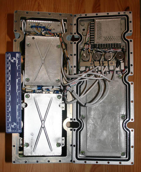 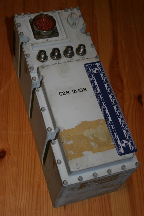
|
garymilgrom
Member Posts: 1966
From: Atlanta, GA
Registered: Feb 2007
|
posted 12-12-2009 10:11 PM
BEAUTIFUL acquisition. Bravo. |
tegwilym
Member Posts: 2331
From: Sturgeon Bay, WI
Registered: Jan 2000
|
posted 12-14-2009 02:08 PM
Nice! When Scott gets his spacecraft all assembled from these parts, I want to be there to see him launch.  |
ilbasso
Member Posts: 1522
From: Greensboro, NC USA
Registered: Feb 2006
|
posted 12-14-2009 10:01 PM
If he can launch it on an S-IB, I've got the ground support equipment! Congrats, Scott! |
SpaceAholic
Member Posts: 4437
From: Sierra Vista, Arizona
Registered: Nov 1999
|
posted 12-27-2009 06:53 PM
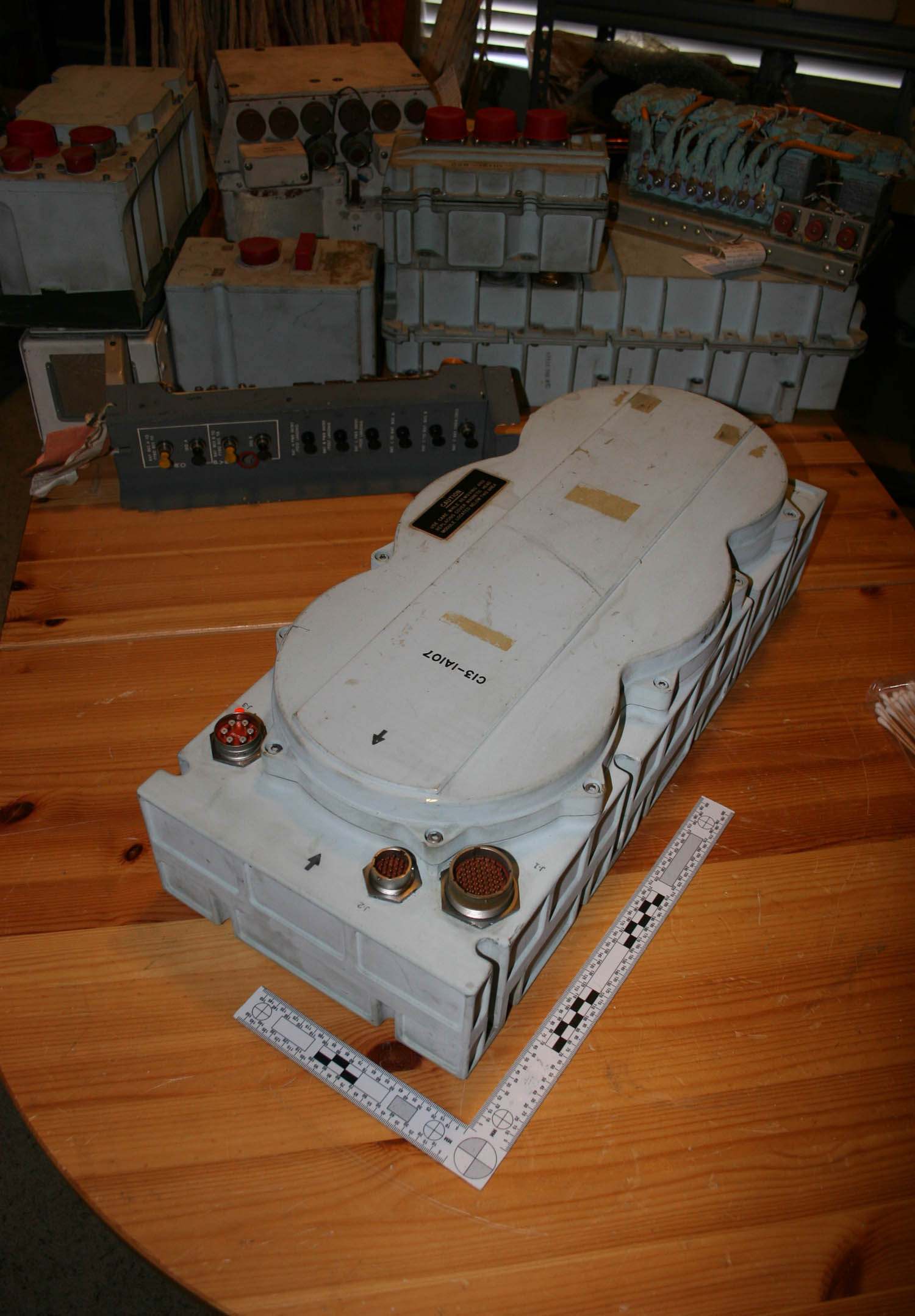
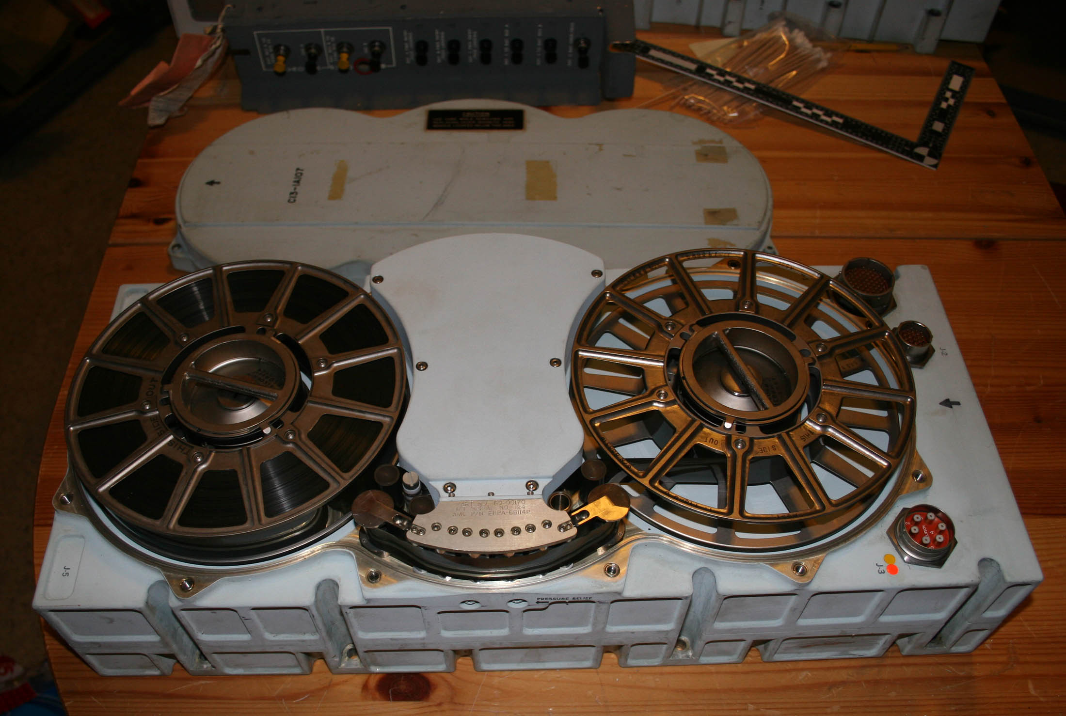
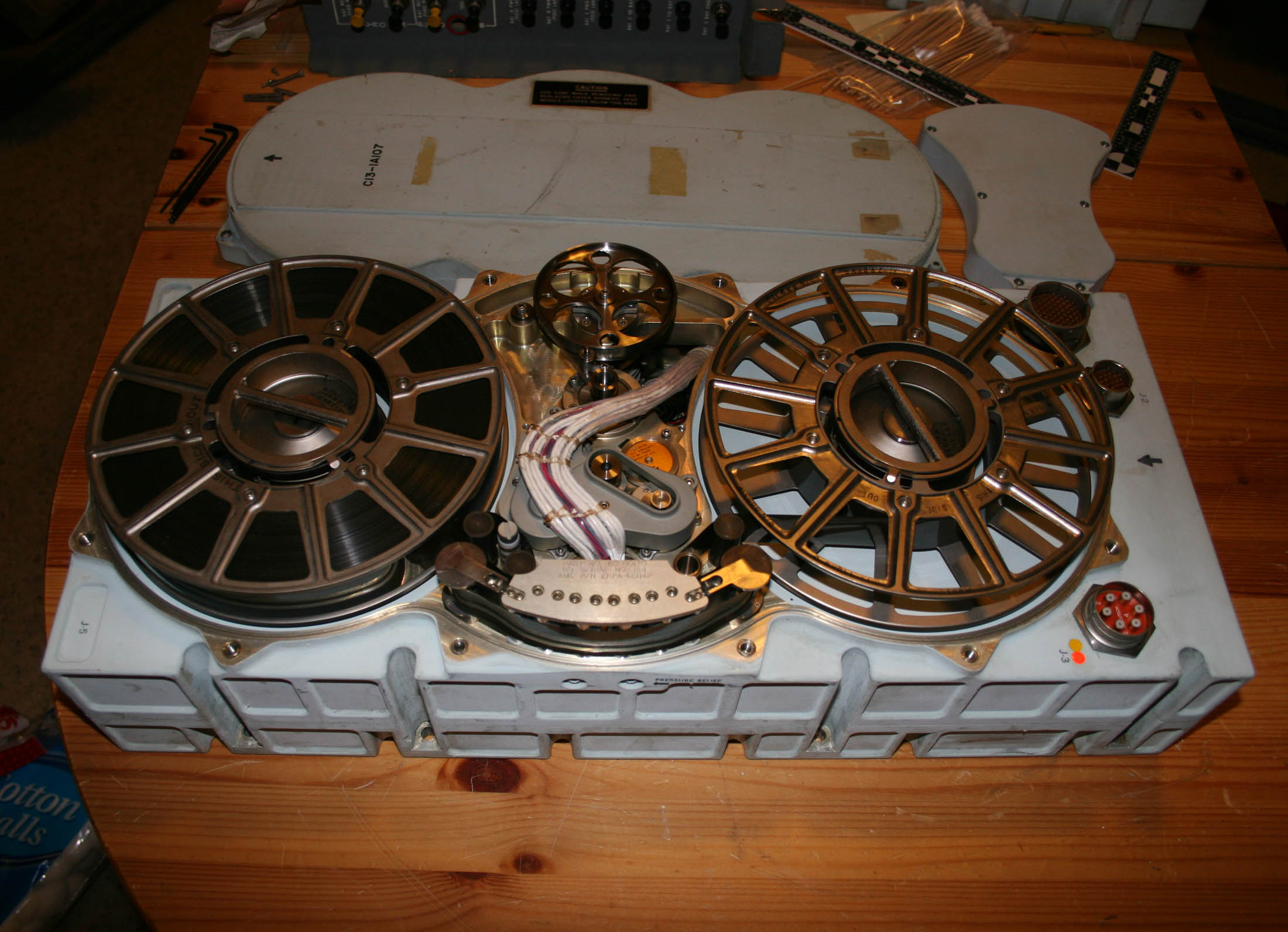
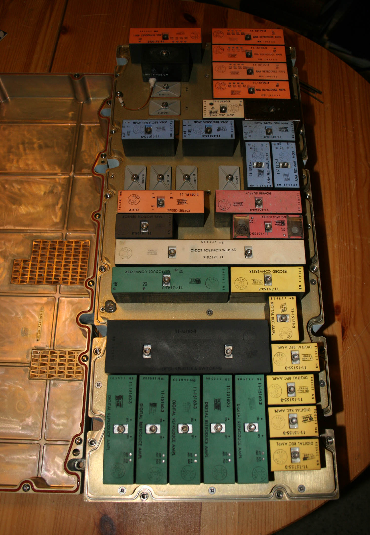
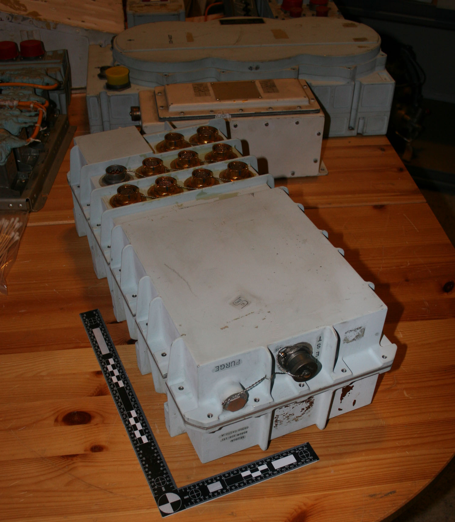
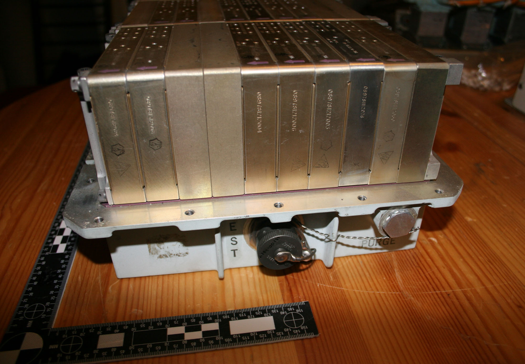
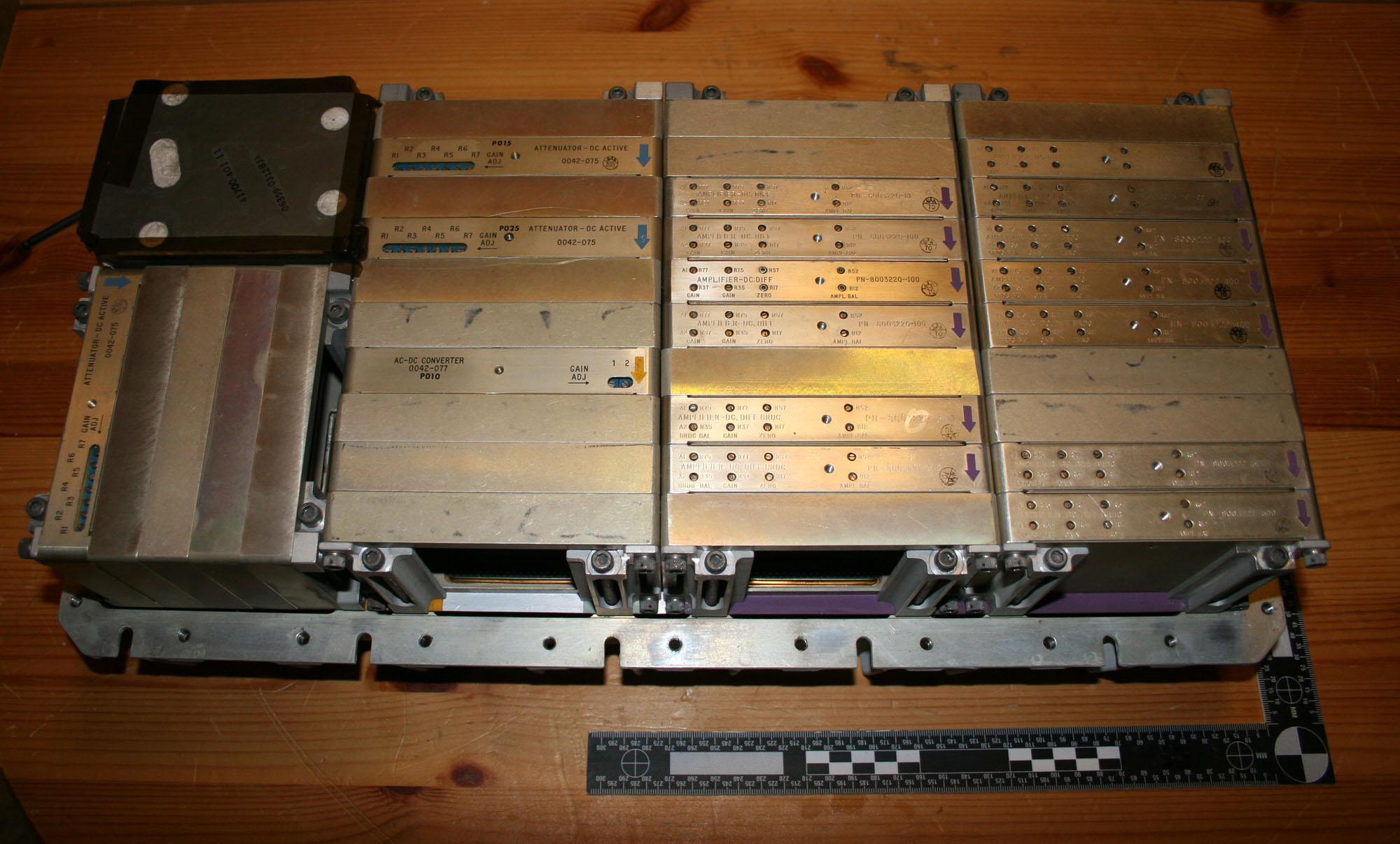
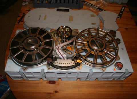
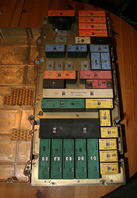
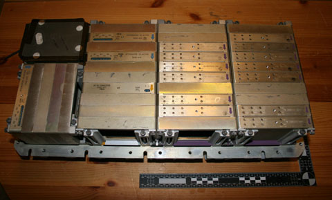
CM Block II Data Storage Equipment (DSE)... these are also referred to by some as the Command Module's black box. The DSE provided for the storage of data for delayed playback and/or recovery with the spacecraft. Information was recorded during powered flight phases and when out of communications and then dumped over the S-Band system back to JSC.The sequence of images that follow show the DSE with cover installed, main cover removed to display the tape/reels, the read/write heads and drive mechanism cover removed, and finally have flipped the unit over and removed the bottom cover to display the individual electronics modules comprising the heart of the DSE. There is a real possibility this artifact was installed in a flight vehicle - if so the tape may still have mission data. Best I can tell this is the first time the internals of a Block II DSE have been made available ...all of the DSE photographs such as the NASA images of DSEs displayed at the bottom of Eric Hartwell's site are in fact Block I DSEs (or derivatives). 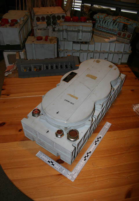 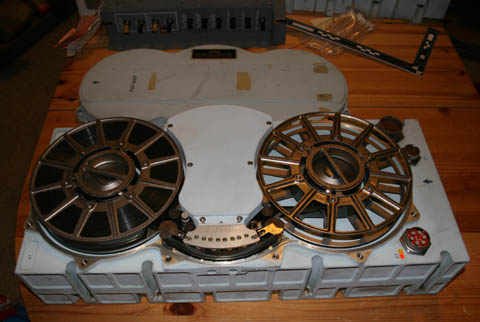
|
SpaceAholic
Member Posts: 4437
From: Sierra Vista, Arizona
Registered: Nov 1999
|
posted 12-27-2009 06:55 PM
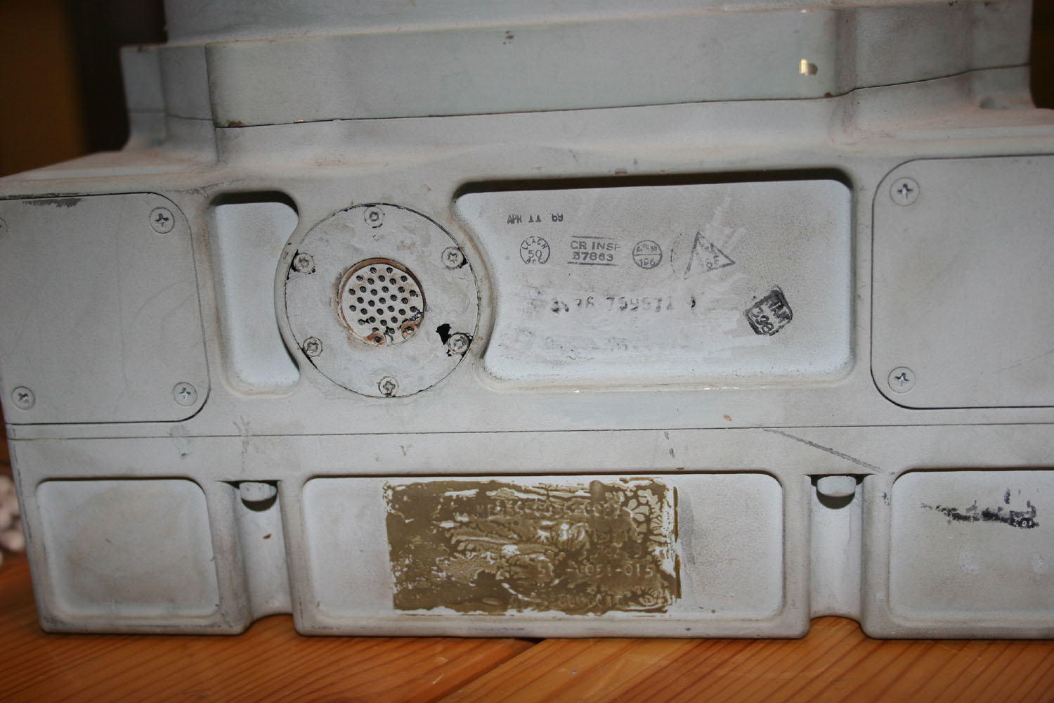
As mentioned above, I beleive there is a reasonable probably the Data Storage Equipment was installed in a flight vehicle and perhaps flown. The rational is based on the fact the DSE was excessed out of North American (many of the CMs underwent postflight inspection and had electronics assemblies removed/retained); as well as the stamps. Unfortunately one of the practices at Rockwell was to scrape tags and stamps off of surplus hardware prior to scrapping at the conclusion of the program. Have however been able to lift information (under magnification using a lope) from the residual text imprint where the label originally existed and as a result it may be possible to establish provenance (click on second image below). Since I have other block II electronics with tags it was relatively easy to affiliate the lifted numbers with the label application. The original tag for this DSE therefore would have read:NAA S&ID PN ME 435-0035-0037
Date of MFR 4/8/69
Collins (or Leach) P/N 514-0051-015
Serial #053338060018 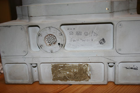 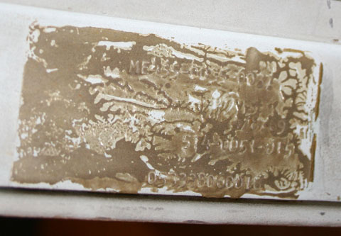
|
DMScott
Member Posts: 354
From: Lexington, MA, USA
Registered: Dec 2005
|
posted 12-28-2009 03:32 AM
Amazing! |
space1
Member Posts: 853
From: Danville, Ohio
Registered: Dec 2002
|
posted 12-28-2009 04:34 AM
Nice work, Scott. Thanks for the great photos. |
ilbasso
Member Posts: 1522
From: Greensboro, NC USA
Registered: Feb 2006
|
posted 12-28-2009 07:26 AM
Flown? Isn't that a nice word for "used", like "previously owned"? I can take that old stuff off your hands for cheap, Scott!Wow!!! |
SpaceAholic
Member Posts: 4437
From: Sierra Vista, Arizona
Registered: Nov 1999
|
posted 12-28-2009 08:15 AM
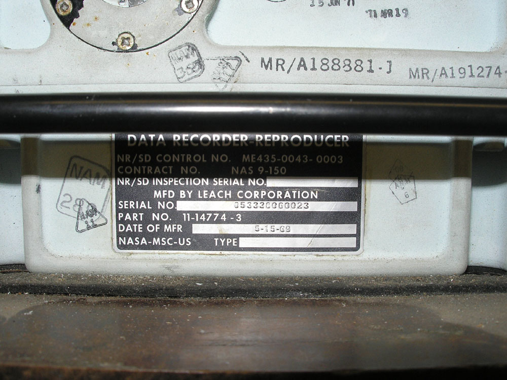
Here's an image received this morning of the tag from Apollo 16 (Casper's) DSE... the last 5 digits of its serial number 60023 (vs 60018 on mine). Supports the theory of a very tight production run and if there is a linear relationship between serial number and application - association with an earlier flight vehicle. 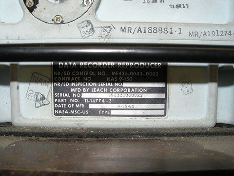 |
SpaceAholic
Member Posts: 4437
From: Sierra Vista, Arizona
Registered: Nov 1999
|
posted 12-28-2009 07:48 PM
"Flight, try SCE to Aux."This is the Signal Conditioning Equipment (SCE) electronics assembly and as fellow collector Tim Collins reminded me today, it was the quick actions of Alan Bean (on queuing from flight controller John Aaron), shifting the SCE to low voltage operation which spared Apollo 12 from the probability of a launch abort after the Saturn V was struck by lighting and telemetry was lost. The SCE transformed signals from the spacecraft sensors annd transducers to basic instrumentation analog voltage measurement, making them compatible for input to the command module displays, telemetry (PCM Telemetry Equipment). Without the input, the Astronauts and JSC were operating in the blind (hence the likelihood of the abort had telemetry not been restored).  
|
SpaceAholic
Member Posts: 4437
From: Sierra Vista, Arizona
Registered: Nov 1999
|
posted 12-29-2009 09:45 PM
Little Box - Big Function!This is the Central Timing Equipment (CTE) which provided the master timing source for just about anything that required it within the Command Module (most of the electronics boxes, and inverters sourced timing from this assembly). It also generated and stored the real-time day, hour, minute and second mission elapsed time for display to the crew and transmittal via the telemetry links to JSC. Unfortunately it is welded shut so am unable to display the internal architecture. 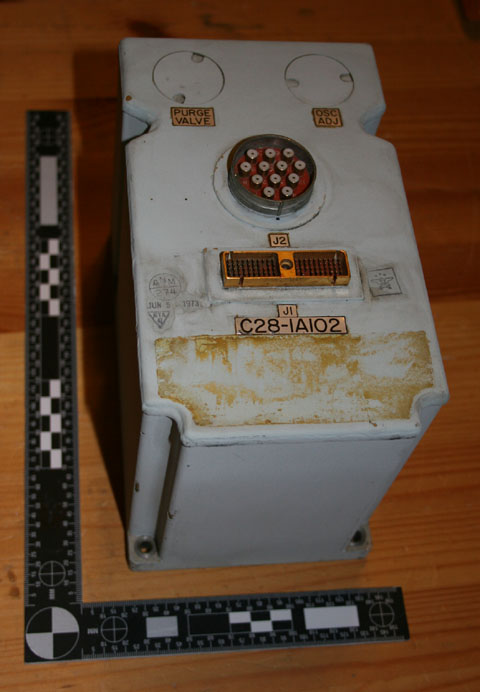 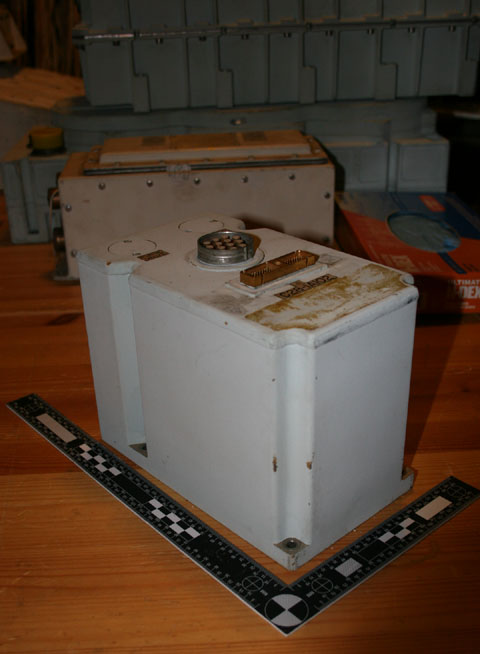
|
SpaceAholic
Member Posts: 4437
From: Sierra Vista, Arizona
Registered: Nov 1999
|
posted 12-29-2009 10:01 PM
Audio Center (ACE). Contains 3 headset audio amplifiers (one for each astronaut) and provided communications paths between the astronauts, astronaut and launch pad personnel, and post-landing recovery frogman; routed audio to the Data Storage Equiment (DSE) discussed in an earlier posting on this thread and routed voice comms to the S-Band / VHF radio's.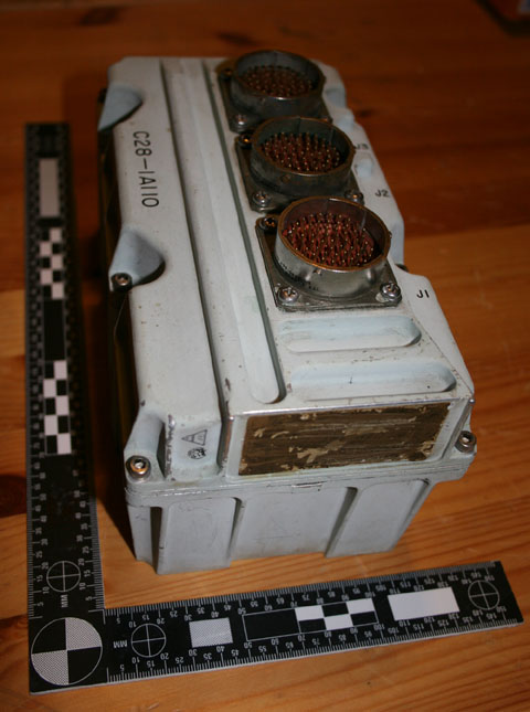 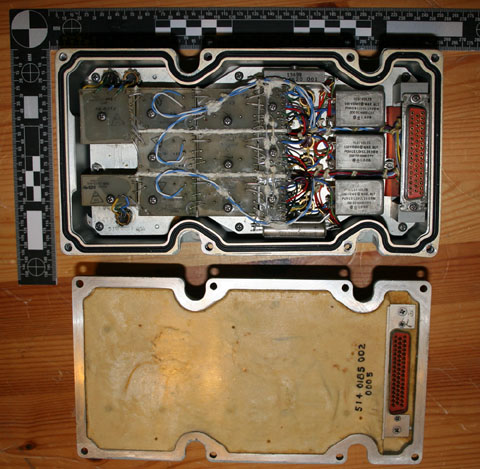
|
davidcwagner
Member Posts: 798
From: Albuquerque, New Mexico
Registered: Jan 2003
|
posted 12-30-2009 01:01 AM
Great items and photos Scott!How much do these items weigh? I'll bet that they are surprisingly heavy by today's standards. |
SpaceAholic
Member Posts: 4437
From: Sierra Vista, Arizona
Registered: Nov 1999
|
posted 12-30-2009 07:42 AM
Weights of the artifacts (many of these haven't yet been discussed on the thread but will be uploaded later in the week). Some could definitely be used as boat anchors. While only single examples are represented in the collection, keep in mind in some instances, multiples were installed on the flight vehicle (for example there were 3 inverters). - Audio Center (ACE) 8 Pounds
- Central Timing Equipment (CTE) 10 Pounds
- Data Storage Equipment (DSE) 40 Pounds
- Earth Landing Sequence Controller (ELSC) 4 Pounds
- Inverter 53 Pounds
- Inverter Control Box 7 Pounds
- Master Events Sequence Controller (MESC) 30 Pounds
- Pre-Modulation Processor 14.5 Pounds
- Pulse Code Modulation (PCM) Telemetry Equipment 42 Pounds
- Pyro Continuity Verification Box 8 Pounds
- Reaction Jet and Engine On-Off Control 30 Pounds
- Reaction Control System Controller (RCSC) 35 Pounds
- S-Band Amplifier 32 Pounds
- Service Module Jettison Controller (SMJC) 10 pounds
- Signal Conditioner Equipment (SCE) 45 Pounds
- Thrust Vector Position Servo Amplifier 22 Pounds
- Unified S-Band (USBE) Transponder 32 Pounds
- Up-Data Link Equipment (UDL) 21 Pounds
- VHF AM Transceiver 13.5 Pounds
- VHF Recovery Beacon 2.7 Pounds
|
SpaceAholic
Member Posts: 4437
From: Sierra Vista, Arizona
Registered: Nov 1999
|
posted 12-31-2009 05:06 PM
Have received a couple of inquiries (and personally curious) as to what schema was applied to the alpha-numeric labels on some of the electronics assembly (EA) covers. It appears they were only assigned to the Telecommunications Subsystem assemblies and I beleived initially the prefix assignments (C13 or C28) were based on the module's location within the CMs lower equipment bay. However after crosslinking the numbers with actual location this is not the case (click on below images). Nor does there seem to be a functional relationship (beyond the fact that all the C13 and 28 are Telecommunications subsystems affiliated).As these EAs periodically pop-up, the images are also offered as an aid to those collectors who run across the Telecomm modules lacking tags and wish to ID them. 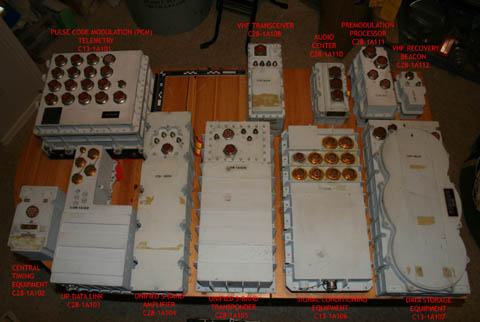 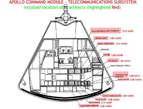
|
SpaceAholic
Member Posts: 4437
From: Sierra Vista, Arizona
Registered: Nov 1999
|
posted 01-02-2010 03:19 PM
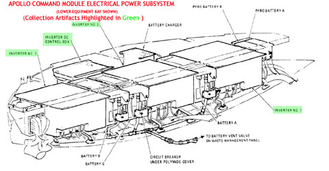
Command Module Inverter and affiliated Inverter Control Box. 3 inverters plus the box installed in the lower equipment bay as shown in the drawing. The Inverters accepted 28 DC voltage produced by the fuel cells and routed through the spacecraft DC Main Bus "A" and "B", porting out 400 cycle 115 volts AC at 1250 amps. The control box was essentially the gate keeper which sat between the DC bus and the inverters, it contains motor driven switches which opened/shut the flow of DC to each of the inverters (normally 2 inverters online producing power, the 3rd in standby). Lots of Ladicote for fire mitigation as one can expect given the high current loads supported. 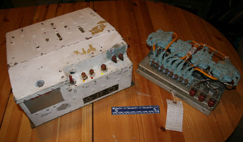 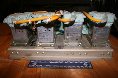
|
AstronautBrian
Member Posts: 287
From: Louisiana
Registered: Jan 2006
|
posted 01-02-2010 05:10 PM
Are you ever so slowly rebuilding an Apollo CM for a secret trip to the Moon? Where do you have the Saturn V stashed? |
bunnkwio
Member Posts: 113
From: Naperville, IL USA
Registered: Jul 2008
|
posted 01-03-2010 12:37 AM
This is an awesome display of CSM equipment! Thank you for in-depth explanation of the pieces as well, Scott!Hmm, the example photo from Apollo 16 DSE shows an ink-stamped date of April '71, or 1 year before launch. Yes, it also shows a Jun '71 stamp on it, but lets have some fun... Given the April '69 stamped date on yours, could it be from Apollo 13?! |
SpaceAholic
Member Posts: 4437
From: Sierra Vista, Arizona
Registered: Nov 1999
|
posted 01-03-2010 12:48 AM
The DSE could conceivably have originated from any CM, Apollo 11 onwards - itching to get my hands on the flight vehicle configuration management docs to cross-reference the unit serial number. Hopefully they will turn up in the future (many of the other electronics assemblies are also potentially excessed from flight vehicles). With respect to the DSE, am trying to track down a Magnetic Field Viewer which will allow for passive viewing of tape data (it will only confirm the presence of data on the tape, not read it). |
SpaceAholic
Member Posts: 4437
From: Sierra Vista, Arizona
Registered: Nov 1999
|
posted 01-04-2010 09:42 PM
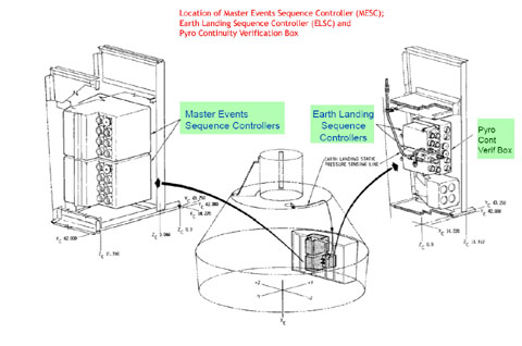
Images of the Master Events Sequencer Controller (MESC), a major component of the Sequential Events Control System Apollo spacecraft subsystem that regulated the automatically sequenced functions during mission ascent, entry, flight and in the event of an abort. These activities included Launch Escape Tower (LET) jettison, Service Launch Adapter (SLA) separation, Lunar Module (LM) separation, Command Module/Service Module (CM/SM) separation and Earth Landing System (ELS) deployment; and during Launch Escape System (LES) actuation and Service Propulsion System abort modes. The MESC, as the Master Controller for the SECS, interfaced with the following controllers: Emergency Detection System (EDS), SM Jettison Controller (SMJC), Command Module Reaction Control System Controller (RCSC), LM Separation Sequence Controller (LSSC), Earth Landing Sequence Controller (ELSC) and the Translation Controller.Obviously all of the above functions were critical not only for mission success but crew survival. The second image of the MESC interior shows an extraordinary potting job with red Dow Corning RTV, the likes of which I have never previously encountered. Third diagram highlights not only the MESC but also the ELSC and Pyro Continuity Box which were co-located in the same (Right Hand) equipment bay (images of those to follow next posts). 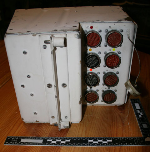 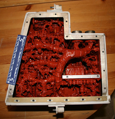
|
ilbasso
Member Posts: 1522
From: Greensboro, NC USA
Registered: Feb 2006
|
posted 01-05-2010 08:18 AM
Looks like some sort of alien nest inside that box! Don't stick your head directly over it! |
SpaceAholic
Member Posts: 4437
From: Sierra Vista, Arizona
Registered: Nov 1999
|
posted 01-05-2010 09:52 AM
Reminded me of a scene from "Angry Red Planet." |
SpaceAholic
Member Posts: 4437
From: Sierra Vista, Arizona
Registered: Nov 1999
|
posted 01-05-2010 10:24 PM
Earth Landing Sequence Controller (ELSC) , Northrup Ventura product (co-developed by that company with the rest of the Command Module Eath Landing System). See MESC diagram above for location of the ELSC. The device was utilized by the SECS to deploy the CM drogue, pilot and main landing parachutes. Notice the Static Air Port on the lower right of the panel in the first image. This was the input for the 24,000 and 10,000 foot baroswitches; their closure armed and subsequently triggered initiation of the 3 mortar deployed pilot parachutes to extract the main canopies. 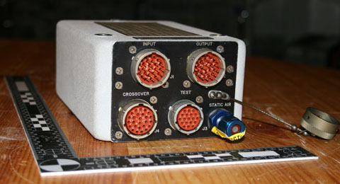 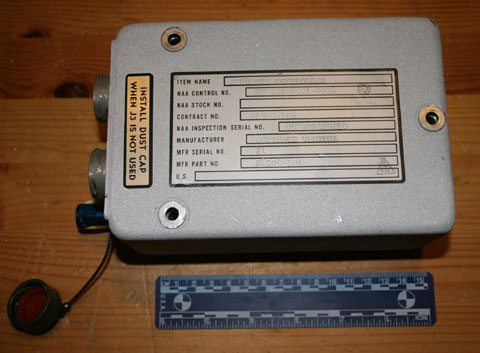
|
Sy Liebergot
Member Posts: 501
From: Pearland, Texas USA
Registered: May 2003
|
posted 01-06-2010 04:44 PM
Great to see the SECS H/W, which was EECOM system responsibility. It was a Criticality One system and was required to have the requisite redundancy. Failure of a Crit One function was catastrophic. That was why there was such a shock when in 1964, I documented that there were five SECS functions that were single point failures. Subsequently, the panel switches were doubled. Also, perhaps generally unknown, contingency procedures were developed to have the crew splice wiring behind panels to recover certain SECS functions. The wiring flew with labeling affixed. I can't recall which functions were affected. Exciting times, for sure. |
SpaceAholic
Member Posts: 4437
From: Sierra Vista, Arizona
Registered: Nov 1999
|
posted 01-06-2010 08:02 PM
Am pleased the MESC brings back some memories Sy... here is another SECS electronics assembly you may also recognize (again co-located in the Right Hand Equipment Bay with the MESC and ELSC) - an Apollo Command Module Earth Landing Pyro Continuity Verification Box (PCVB), operated in series with the ELSC to monitor the pyrotechnics associated with the Apex Cover, and parachute deployment mortars - included a GSE access connector for ground checkout of ELS pyrotechnics.System redundancy achieved in a single unit (unlike the MESC/ELSC which had two boxes per subsystem). 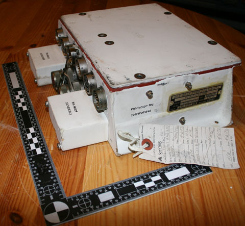 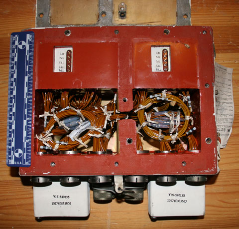
|
SpaceAholic
Member Posts: 4437
From: Sierra Vista, Arizona
Registered: Nov 1999
|
posted 01-08-2010 07:05 PM
Another CSM Sequential Events Control System (SECS) component - this one responsible for automatic separation control of the Service Module from the Command Module. As shown in the diagram, the Service Module Jettison Controller (SMJC) was actually mounted in the forward bulkhead of the Service Module and supported by battery power so that it could autonomously perform its function even after CM separation. Physical separation required severing of all the connections between the modules, transfer of electrical control, and firing of the Service Module Reaction Control System to increase the distance between the CM and SM. After separation, the SMJC continued to send commands to the solenoids controlling propellant flow into the Service Module R-4D's (Reaction Control engines), propelling the SM away from the CM. 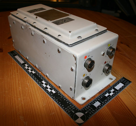 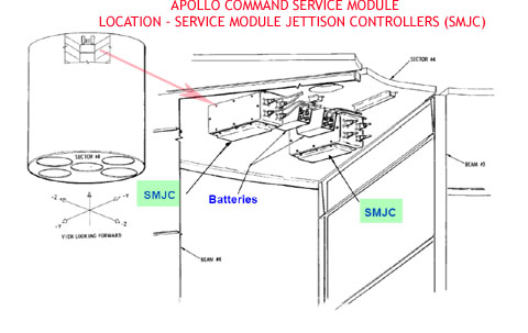
|
SpaceAholic
Member Posts: 4437
From: Sierra Vista, Arizona
Registered: Nov 1999
|
posted 01-10-2010 07:07 AM
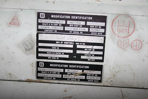
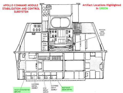
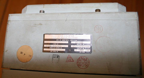
Reaction Jet and Engine On-Off Control Assembly (RJ/EC) manufactured by Honeywell - part of the CSM Stabilization and Control System, responsible for translating Service Propulsion System (SPS) Main Engine and CM/SM Reaction Control System (RCS) firing commands originated from either the vehicle flight computer or manually from the astronaut (using the Translation Controller) to firing impulses. The RJ/EC accepted the firing commands and outputted 28 volt dc which opened the affiliated SPS/RCS solenoids on each of the engines, flowing propellant and thus firing the main engine and/or R-4Ds (Service Module)/SE-8's (Command Module) as applicable. In effect this box functioned as an electronic "gas pedal".Per the diagram, the unit was installed in the lower equipment bay (the diagram also shows the TVSA highlighted which will be addressed next entry). High probability both the RJ/EC and TVSA to follow were flown. 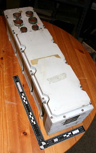 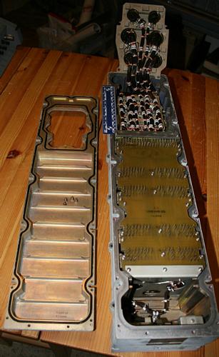
|
SpaceAholic
Member Posts: 4437
From: Sierra Vista, Arizona
Registered: Nov 1999
|
posted 01-10-2010 05:13 PM
Another Stabilization and Control Subsystem assembly (location shown in previous diagram). The Thrust Vector Position Servo Amplifier (TVSA) provided the electrical interface between the command electronics and gimbal actuator for positioning the Service Propulsion System (SPS) main engine. The TVSA (1) received main engine actuator position and deflection rates (velocity) and forwarded that information to the Gimbal Position/Fuel Pressure Indicator on the main display console; and (2) interpreted both Automatic Thrust Vector commands issued by the Command Module Computer as well as manual commands originated by the crew inputs on the Rotation Controller, and converted them to a clutch current which resulted in actuator deflection and as a result, gimbaling of the SPS main engine.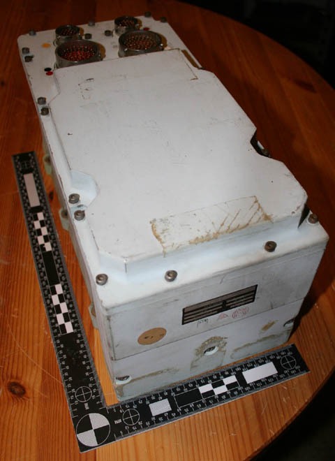 
|
lukr
New Member Posts: 5
From: Melbourne, Australia
Registered: Feb 2018
|
posted 01-10-2019 05:18 AM
Scott, great admirer! I have been following the forum mostly as a passive participant. I hope you don't mind me asking a question regarding the drawing you posted of the location of the RCSC in the aft external equipment bay.For a 1:12 paper model I am hoping to complete, I have found more technical drawings of the cabling, tanks and RCS in that compartment. I know there were other instruments stored there as well (like the RCSC clearly) but they are not on those drawings. Any pointers as to where I might find more reference information? Thanks in advance! |
SpaceAholic
Member Posts: 4437
From: Sierra Vista, Arizona
Registered: Nov 1999
|
posted 01-10-2019 05:40 AM
Drawings toward the tail end of the CSM universal systems handbook have relatively good fidelity depictions of architecture. Send me a note directly and we can coordinate file transfer (too large to email). |