November 2, 2007 — In 1970, the solution involved duct tape, a flight manual's cover, a plastic bag and a sock.
Three years later, it was a nylon and mylar umbrella that was assembled with a sewing machine. In 1985, although unsuccessful, the answer was two makeshift flyswatters.
And on Saturday, should NASA proceed as planned, the success of its current mission will rely on six cufflinks.
But it's not like the 10 astronauts in orbit can just rent the fasteners from the local tuxedo shop. To save the space station on which they all currently inhabit, they needed to assemble their repair tools from the spare parts launched for just such an occasion.
A rip in an array
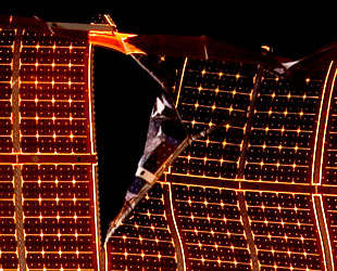
The larger of two tears in the array (Image: NASA) |
Earlier this week, after successfully repositioning a truss and solar array assembly to its permanent berth on the International Space Station, the crew of shuttle Discovery and the outpost's own residents set about deploying the segments' pair of power-generating wings. The first array extended without issue, but as the second was almost at its full length, the station's commander halted the deploy after observing a tear that was forming mid-way along its 110-foot length.
The damage, which upon closer inspection was found to be two tears — a 2.5 foot rip and another about one-third the size — was a serious concern. The ISS was already at a power handicap as a faulty joint was preventing one set of its arrays from rotating to track the Sun. Now, with the second set of arrays unable to extend completely, it too would be unable to follow the power-providing rays of our nearest star. Although there was enough electricity to support its current configuration, without repair, the torn wing was threatening future expansion, including the long awaited launch of European and Japanese science labs.
Flights controllers quickly went to work around the clock to develop a daring plan: using a 50-foot boom designed to inspect the shuttle for damage and the station's own 50-foot robotic arm, an astronaut will be positioned at the site of the tear, where he will attempt to clear a snagged guide wire believed to be the source of the damage, and then repair the torn hinge by inserting splints, referred to as cufflinks, to stabilize the array such that it can be fully extended. Were it not enough that the boom has never been used for such a purpose, or that the astronauts were never trained for such a maneuver, the array, though torn, will still be running a current such that it poses a low but real risk of shocking the spacewalker.
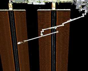
Station arm to shuttle boom to astronaut at array (Image: NASA) |
MacGyver's mission
Well before Discovery launched to space on October 23, STS-120 commander Pam Melroy dubbed one of her six crewmates as the astronaut version of the resourceful TV character MacGyver. Speaking of her mission specialist from the European Space Agency, Melroy recalled telling Paolo Nespoli to take all his tools with him to space.
"I encouraged him to take one of everything because I am sure he's going to build something in space with it."
As chance would have it, Melroy would be partially right. Though Nespoli will support Scott Parazynski and Doug Wheelock during the spacewalk from his vantage point inside, it was Discovery's pilot George Zamka along with ISS Expedition 16 commander Peggy Whitson who were called upon on Thursday to exhibit their inner-MacGyver.
Using strips of aluminum, a hole punch, a bolt connector and 66 feet of wire, along with detailed instructions sent by mission control (see below), the duo assembled half a dozen space station-saving cufflink contraptions. If all proceeds as planned, Parazynski, suspended at the end of the boom-arm assembly, will slip the cufflink-like tabs through holes in the array's blanket, enabling it to support the tension exerted when the solar wing is fully extended.
Like the sock/duct tape/plastic bag solution that allowed a square-shaped carbon dioxide scrubber to fit in a round hole aboard Apollo 13, the success of the cufflinks won't be known until they are installed, but those who worked to devise the fix are optimistic that failure is not an option.
"We're faced with a difficult situation," said experienced spacewalker David Wolf. "I think we're onto a solution that should work and get us pretty close to a permanently acceptable situation."
How exactly does one assemble a space station saving cufflink from spare parts? Very carefully, as appears to be the case in this, the seven-part instructions that were uplinked to the astronauts, complete with illustrations for key steps. Warning: it's acronym laden (e.g. FOD=foreign object debris, MCC-H=Mission Control Center-Houston) and with the possible exception of the ink marker and two ziplock bags, calls for items not usually found around the house, so it's probably best kids, not to try this at home.
Click on images to enlarge.
16-0156 (MSG 106)
Solar Array Hinge Stabilizer Construction
OBJECTIVE
Construct three sizes of Solar Array Hinge Stabilizers: two Long (64-3/4 inches), two Medium (63-3/8 inches) and two Short (35-1/4 inches). Hinge Stabilizers will be constructed out of components of the Clamp and Bracket Kit and Large and Small Gauge Pin Kits. The Hinge Stabilizers work similarly to a tuxedo cufflink; each end will be fed through a hole in the Solar Array on opposite sides of the separated hinge.
LOCATION:
Lab, Node 2
CREW:
Two
PARTS:
None
MATERIALS:
Sharpie
Ziplock Bag (two)
Kapton Tape
EVA Tape P/N P-213
ISS Pin Kit: (two) P/N SJG33110644-301
Page 3:
12 Ga Wire (50 feet) (need approximately 66 feet total)
Clamp and Bracket Kit: P/N SJG33112385-301
0.03" x 4" x 12" Aluminum (two)
Large Gauge Pin Kit: P/N SJG33115400-301
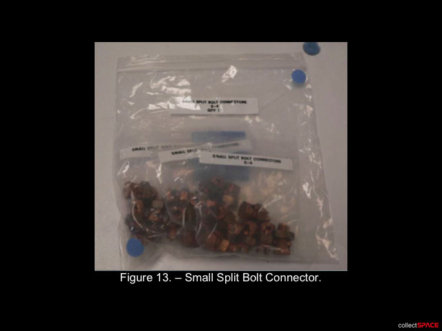
Small Split Bolt Connector P/N S-4
TOOLS:
Eye Protection
DCS 760 Camera
ISS Vacuum Cleaner
MWA Utility Kit: P/N SJG33110310-301
Track Restraint (two) P/N SEG33110158-301
PC Circuit Board Clamp (two) P/N SEG33110160-301,
-303)
Clamp and Bracket Kit: P/N SJG33112385-301
Tin Snips
Hand Punch
Hand Punch Key
9/32" Punch Insert (engraved "281")
9/32" Punch Die (engraved "281")
ISS IVA Toolbox:
Drawer 2:
9/16" Socket, 3/8" Drive
11/16" Socket, 3/8" Drive
Ratchet, 3/8" Drive
(40-200 in-lbs) Trq Wrench, 3/8" Drive
Drawer 4:
Wire Cutters
Drawer 5:
Tape Measure
Steel Rule
Breaker Bar, 3/8" Drive
File Set, Small
Small Round File
Red File Handle
File Set, Large
Large Hand File
Black File Handle
REFERENCED PROCEDURE(S):
A.2.6 Maintenance Work Area (MWA) Installation
1. CONFIGURING MWA
1.1 Clear all equipment from MWA Work Surface Area.
1.2 Setup MWA Containment System with ISS Vacuum Cleaner. If necessary, refer to {A.2.6 Maintenance Work Area (MWA) Installation}, (SODF: IFM - In Flight Maintenance: Reference: Appendix A: ISS IVA Tools).
1.3 Retrieve Track Restraints and PC Circuit Board Clamps from MWA Utility Kit.
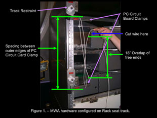
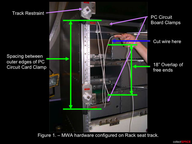
1.4 Set up Track Restraints and PC Circuit Board Clamps on rack as shown in Figure 1.
Recommend using ZSR rack in Node 2.
Spacing between outer edges of PC Circuit Board Clamps will be configured to the following lengths:
Long Hinge Stabilizer: 64-3/4 inches (two)
Medium Hinge Stabilizer: 63-3/8 inches (two)
Short Hinge Stabilizer: 35-1/4 inches (two)
All lengths have a tolerance of +/- 0.25 inches.
2. CUTTING ALUMINUM STRIPS
2.1 Retrieve 4" x 12" Aluminum stock in Clamp and Bracket Kit.
NOTE:
Each Hinge Stabilizer built will require 4 aluminum strips.
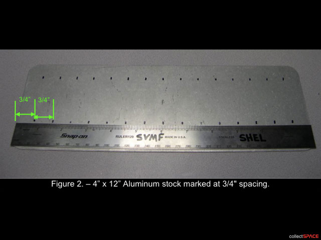
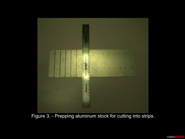
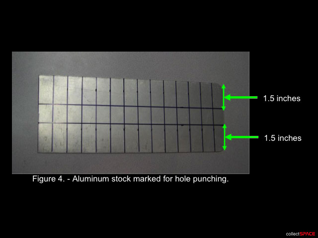
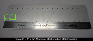
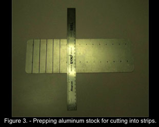
2.2 Mark aluminum stock to create strips measuring 4" long x 3/4" wide (Sharpie, Steel Rule).
Refer to Figures 2 and 3.
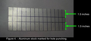
2.3 Mark aluminum stock 1.5" from each long edge.
These lines will later serve as guide for punching holes in the aluminum strips.
WARNING:
This procedure will generate metal FOD, sharp edges, and loose wire ends. Usage of eye protection is required through step 4. If possible, steps should be performed inside MWA Containment System with ISS Vacuum Cleaner running.
2.4 Don Eye Protection.
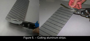
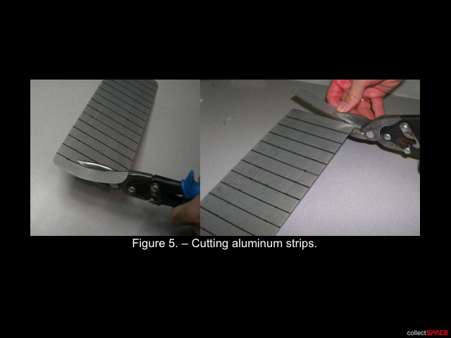
2.5 Cut a total of 26 aluminum strips (Tin Snips).
This includes two spare strips.
2.6 If bent during cutting process, flatten aluminum strips by hand.
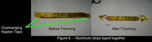
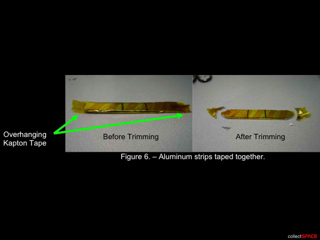
2.7 Tape aluminum strips together in stacks of two, creating a single aluminum strip measuring 4" long x 3/4" wide x two layers thick.
Ensure at least one aluminum strip has visible hole-punch centering markings after taping.
When taping, use one layer of Kapton Tape, allowing approximately 0.5" excess tape to overhang edge to capture FOD in next step.
Refer to Figure 6.
2.8 Trim corners of each metal strip at a 45 degree angle to remove sharp edge (Tin Snips).
Allow Kapton Tape to contain FOD.
Refer to Figure 6.
2.9 File sharp edges created by cutting (MWA Containment System, Large Hand File, Black File Handle, ISS Vacuum Cleaner).
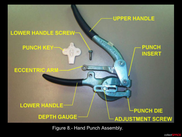
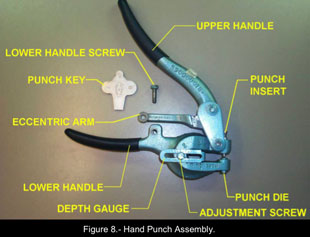
3. CONFIGURING HAND PUNCH
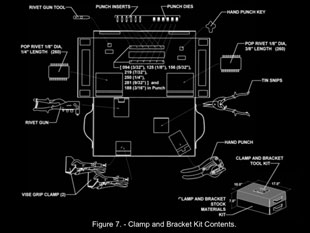
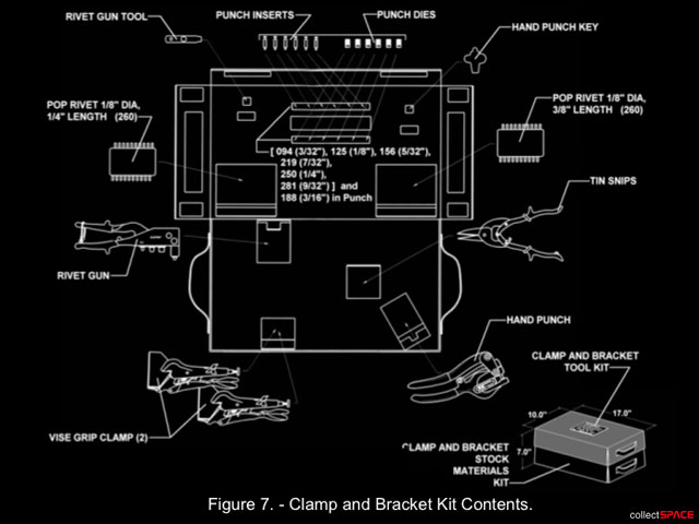
3.1 Retrieve Hand Punch and Punch Key from Clamp and Bracket Kit.
Refer to Figures 7 and 8.
3.2 Use Punch Key from lid of Clamp and Bracket Tool Kit to loosen, remove Lower Handle Screw (non-captive).
Temporarily stow.
Refer to Figure 8.
3.3 Rotate Upper Handle and Eccentric Arm until Eccentric Arm is back far enough for adequate clearance to allow removal of Punch Insert.
Refer to Figure 8.
3.4 Remove Punch Insert and swap out with 9/32" Punch Insert (engraved "281") from stowage in lid of Clamp and Bracket Tool Kit.
Refer to Figures 7 and 8.
3.5 Align top of Punch Insert with groove in Eccentric Arm while pulling up on Upper Handle to seat Punch Insert.
Align screw hole in end of Eccentric Arm with hole in Lower Handle to allow installation of Lower Handle Screw using Punch Key.
3.6 Use Punch Key to loosen Punch Die from bottom of Lower Handle and swap out with 9/32" Punch Die (engraved "281") (same size as Punch Insert) from stowage in lid of Clamp and Bracket Tool Kit.
3.7 Retrieve one taped aluminum strip pair, locate middle of Hand Punch alignment mark created in step 2.3 (3/8" from long edge).
Mark with Sharpie, Steel Rule.
3.8 Insert aluminum strip into Hand Punch, centering punch location with markings from steps 3.7 and 2.3.
Lightly squeeze Hand Punch to hold aluminum strip.
3.9 Adjust Depth Gauge to edge of aluminum strip. Tighten Adjustment Screw (Punch Key).
This will center the punch along the width of the metal strips for subsequent punches.
Refer to Figure 8.
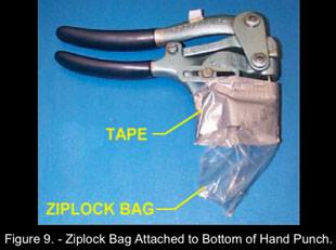
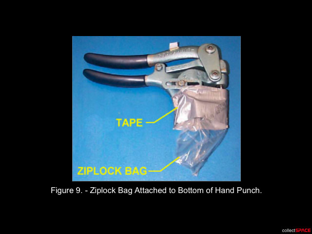
3.10 Tape small Ziplock Bag over bottom of Hand Punch beneath Punch Die to contain debris (Gray Tape, Ziplock Bag).
Refer to Figure 9.
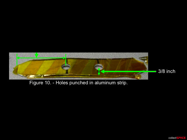
4. PUNCHING HOLES IN ALUMINUM STRIPS
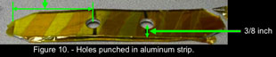
4.1 Punch two holes in taped aluminum strip.
Center holes along width of strip, and align center of Hand Punch over alignment mark created in step 2.3.
4.2 File away any sharp edges caused by Hand Punch (Small Half Round File, Red File Handle, ISS Vacuum Cleaner).
4.3 Wrap each aluminum strip with one additional layer of Kapton Tape.
4.4 Locate EVA Tape with part number P-213.
4.5 Wrap each aluminum strip with two layers of EVA Tape, tapering the ends.
4.6 Push/cut through tape at each hole location (Small Round Hand File, Red File Handle).
4.7 Temporarily stow completed aluminum strips in Ziplock Bag.
4.8 Repeat step 4 for all taped aluminum strips.
4.9 Doff Eye Protection.
5. HINGE STABILIZER WIRE PREPARATION
5.1 √MCC-H to verify Hinge Stabilizer sizes in step 1.4 are correct.
5.2 Retrieve 12 Ga Wire from ISS Pin Kit.
5.3 Verify Track Restraints and PC Circuit Board Clamps properly configured for desired Hinge Stabilizer size.
Refer to step 1.4.
5.4 Wrap 12 Ga Wire around PC Circuit Board Clamps, allowing approximately 18 inches of overlap of the free wire ends.
Cut 12 Ga Wire (Spliced Crimp Tool)
Refer to Figure 1.
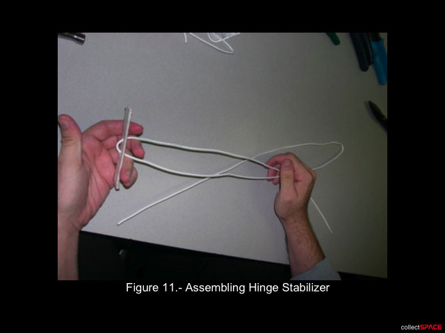
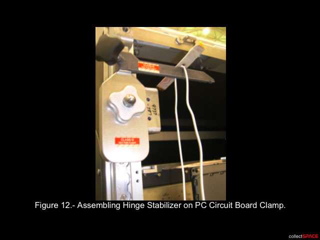
6. ASSEMBLING HINGE STABILIZER
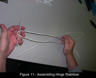
6.1 Feed wire through holes in aluminum strips as shown in Figure 11.
6.2 Pull wire through aluminum strips until seated in wire bend.
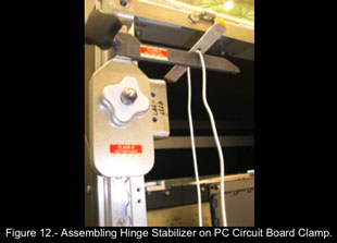
6.3 Reposition Hinge Stabilizer aluminum strips on PC Circuit Board Clamps to verify correct sizing (Tape Measure).
Adjust lengths as required.
Refer to Figure 12 and step 1.4.
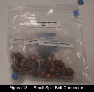
6.4 Retrieve Ziplock Bag of Small Split Bolt Connectors (P/N S-4) from Large Gauge Pin Kit.
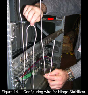
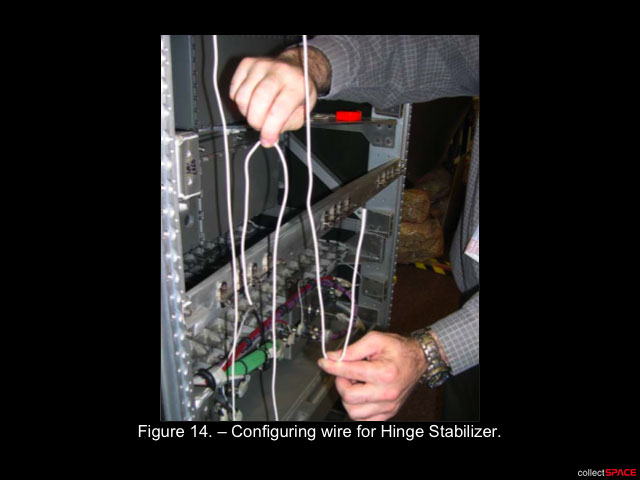
6.5 Fold free wire ends as shown in Figure 14.
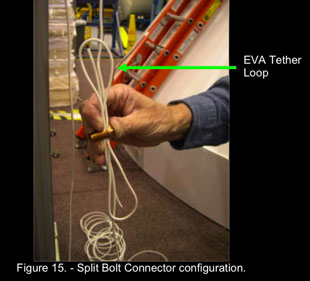
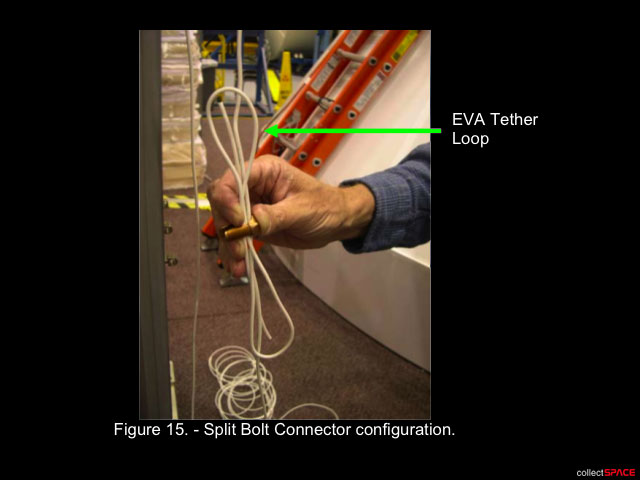
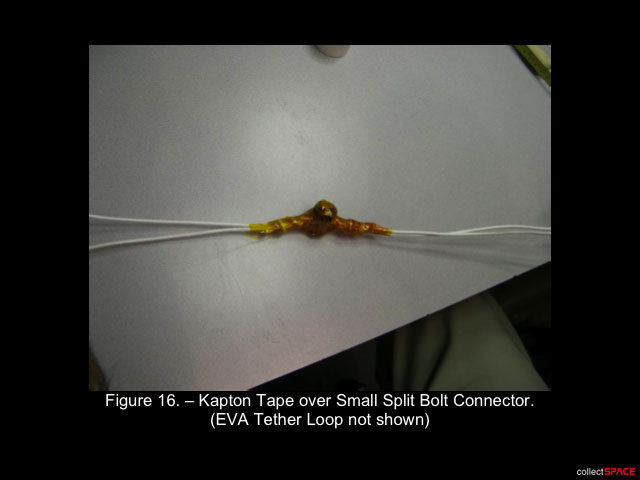
6.6 Feed wire into Split Bolt Connector as shown in Figure 15.
6.7 Tighten Split Bolt Connector Nut (Bolt: Breaker Bar, 3/8" Drive; 9/16" Socket; Nut: Ratchet, 3/8" Drive; 11/16" Socket).
6.8 Perform final length verification (Tape Measure).
Adjust as required.
Refer to step 1.4 for proper length.
6.9 On MCC-H GO, Torque Split Bolt Connector Nut to 160 in-lb (Bolt: Breaker Bar, 3/8" Drive; 9/16" Socket; Nut: (40-200 in-lbs) Trq Wrench, 3/8" Drive; 11/16" Socket).
6.10 Photo document each torqued Split Bolt Connector (DCS 760 Camera).
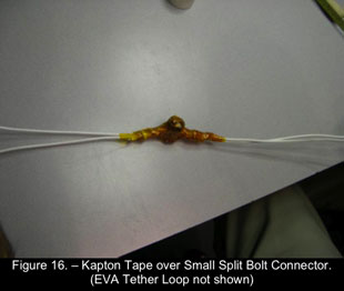
6.11 Wrap Split Bolt Connector with Kapton Tape, leaving sufficient wire exposed for EVA tether point.
6.12 Wrap Split Bolt Connector with two layers of EVA Tape (P/N P-213)
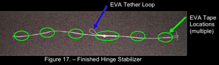
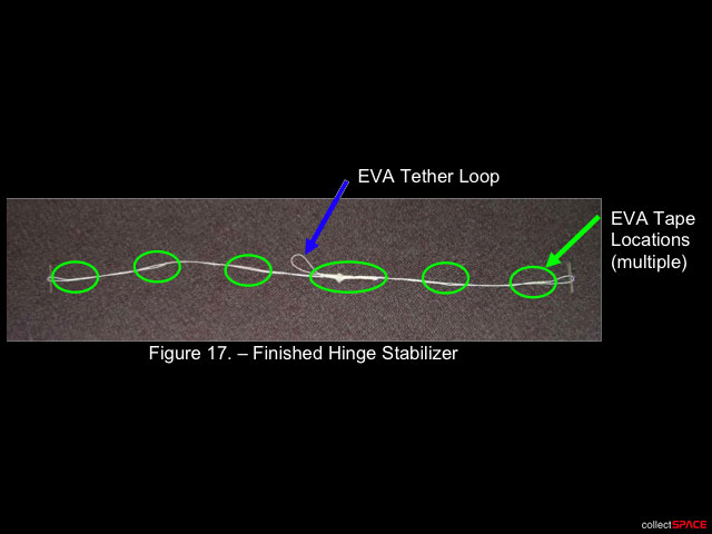
6.13 Wrap wire with two layers of EVA Tape approximately 2 inches from aluminum strip to prevent excess movement of aluminum strip.
Wrap wire with two layers of EVA Tape approximately every 12 inches to prevent wires from seperating.
Refer to Figure 17.
6.14 Photo document each completed Hinge Stabilizer (DCS 760 Camera).
6.15 Label taped aluminum strips "L", "M", or "S", according to Hinge Stabilizer size (Sharpie).
6.16 Repeat steps 5 and 6 for remaining Hinge Stabilizer.
7. CLEANUP
7.1 Restow MWA Containment System, tools, equipment. If necessary, refer to {A.2.6 MAINTENANCE WORK AREA (MWA) INSTALLATION}, (SODF: IFM: REFERENCE: APPENDIX A: ISS IVA TOOLS).
7.2 Check for FOD near worksite.
7.3 Report approximate remaining quantity of 12 Ga Wire in ISS Pin Kit.
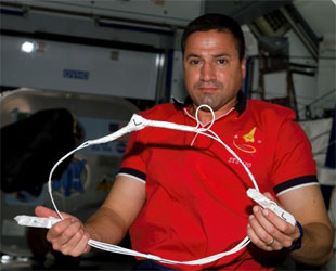
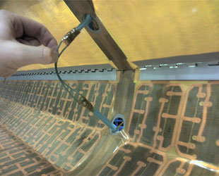
George Zamka, STS-120 pilot, holds a completed cufflink in the Harmony node of the International Space Station. (NASA) |