posted 06-24-2016 12:07 AM


Knowing that many cS members are fascinated with "behind the scenes" stories including stories of a technical nature, I submit the following: "If you can't bring the OPS to the LM, bring the LM to the OPS. Well, not exactly!"
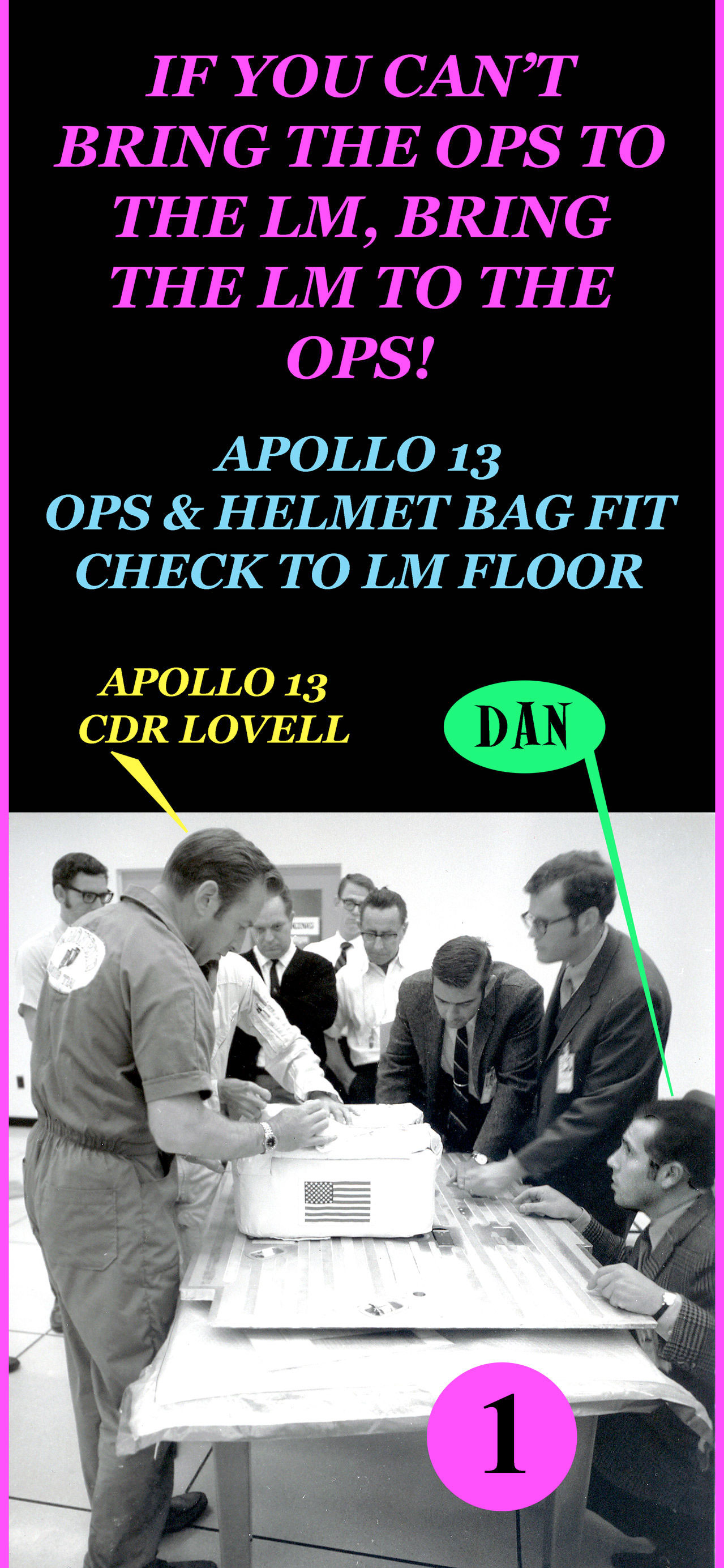
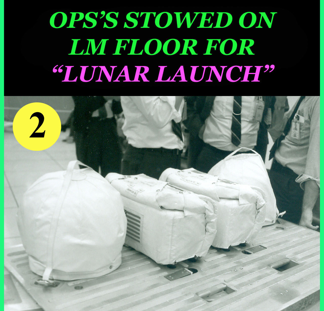
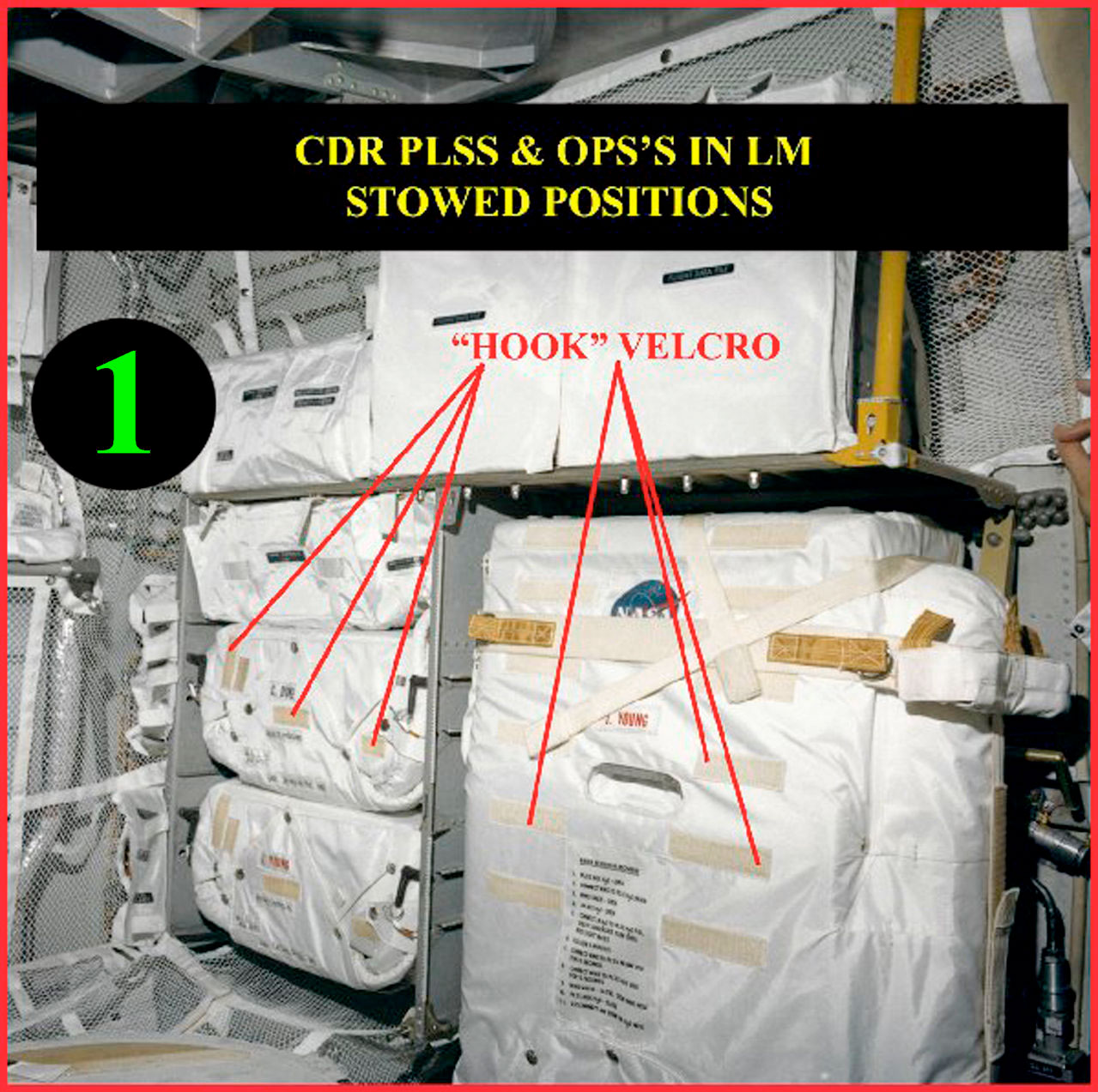
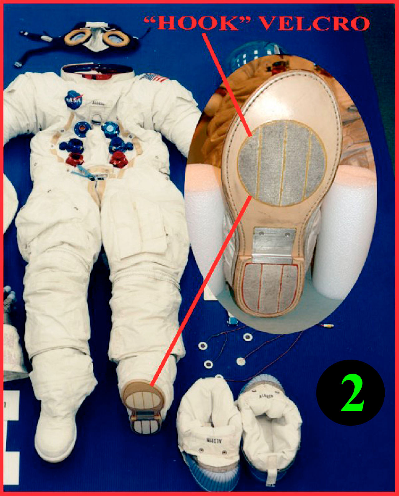
A very important mission requirement was hardware interface fit checks to verify hardware compatibility between different contractors. Photos 1 and 2 below represent an "interface fit check" between Hamilton Standard's Oxygen Purge System (OPS) and Grumman's lunar module (LM) floor. Also, between ILC's helmet stowage bags and Grumman's LM floor.
The first objective of the fit check was to give the Apollo commander and lunar module pilot (in this case, Apollo 13 CDR Lovell and LMP Haise) the opportunity to install both OPSs to the LM floor (Photo 1). The second objective was to confirm compatibility of the OPS mounting feet and locking pin with the LM floor.
For each mission, the OPS fit check was performed in the Kennedy Space Center crew training building. How was that possible, you might ask! As the title of the first photo suggests, "If you can't bring the OPS to the LM, bring the LM to the OPS." Specifically, bring the LM floor to the crew training building.
The stowage configuration with the two OPSs mounted to the LM floor as in the first two photos was the LM "lunar launch" configuration. Therefore, the LM lunar pre-launch stowage configuration necessitated that the crew stow the OPSs and therefore the required LM crew involvement in the OPS stowage fit check procedure.
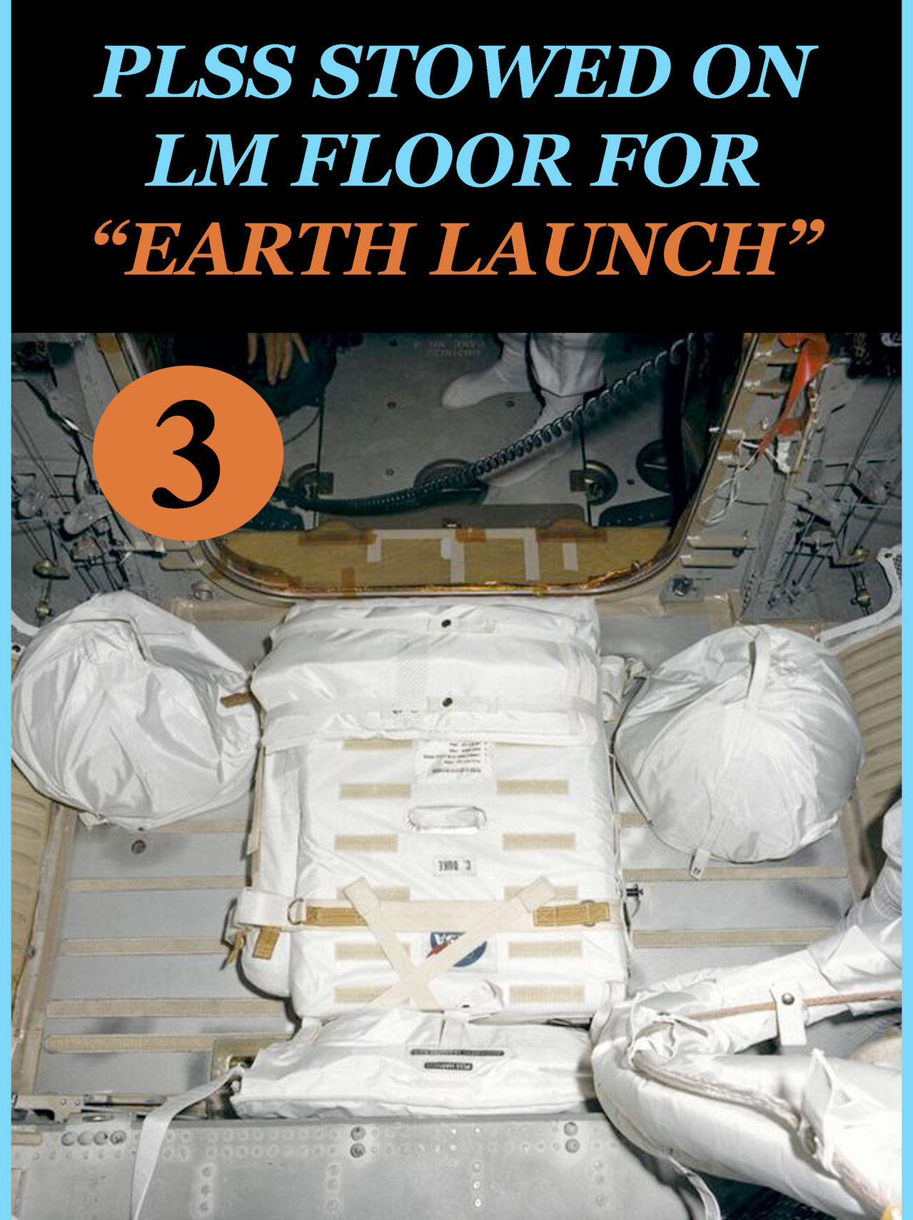
Photo 3 shows the LM floor "Earth launch" configuration with the LMP PLSS stowed on the LM floor. Fit checking the LMP PLSS to the LM floor was also performed at the same time as the OPS fit checks (note that Photo 3 shows the LMP PLSS stowed on the LM floor in the LM). The PLSS "fit check" procedure with the crew was accomplished along with the OPS fit check in the KSC crew training building. Despite the fact that the crew was not required to stow the PLSS on the LM floor after Lunar landing, they were required to remove the PLSS from the LM floor before EVA. Therefore, the crew practiced PLSS removal from the floor during the fit check.
Throughout crew training EVA exercises, we experienced a number of OPS to PLSS mounting problems. As PLSS/OPS Crew Training Mission Manager, I was in the unique position of being able to document crew training OPS problems to determine their possible impact on "flight" hardware.
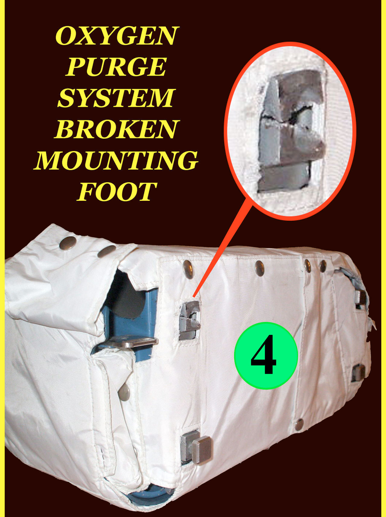
One major problem identified during EVA crew training was a broken OPS foot as seen in Photo 4 and both broken and misaligned OPS feet in Photo 5. The OPSs in the photos are crew training (non flight) OPSs that were used many times over for multiple mission EVA training exercises. Knowing that the flight OPSs would be subjected to OPS to LM floor fit checks and flight OPS to flight PLSS mountings during pre and post EVA training procedures, I, of course, was concerned that problems experienced during crew training did not occur during flight mission procedures.
Before presenting the problem to Hamilton Standard headquarters in Windsor Locks, Conn. and to NASA Crew Systems Division at KSC and Houston, I carefully looked at the problem with the intent of identifying possible contributing factors. Following are my identified possible factors pertaining to OPS to PLSS and OPS to LM floor mounting problems in no specific order of priority:
- Alignment of PLSS mounting brackets and OPS mounting foot brackets:
Looking at Photo 5 Insert C, the PLSS OPS rectangular mounting brackets (identified with the green OPS feet guide channels) along with the OPS mounting foot brackets (Photo 5 Insert Photos A and B) it is clear that both the PLSS and OPS brackets had to be properly aligned so that the OPS Feet would slide into the PLSS guide channels (green) without interference that could have resulted in a cracked and/or broken OPS foot or feet.
- Alignment of OPS male Locking Pin to both the PLSS and LM floor female locking pin receptacles:
Photo 5, Inserts B and C show the location of the OPS locking pin and its PLSS female receptacle (yellow).
- OPS thermal cover material positioned incorrectly around OPS mounting feet:
As can be seen in Photo 4, the OPS thermal cover surrounding the perimeter of the four OPS feet must be positioned so that the thermal cover material does not slip down over part of a foot creating a resistance to the OPS foot/PLSS mounting bracket installation process.
- Incorrect Astronaut installation:
Without looking at the OPS feet and PLSS mounting bracket a crew member could conceivably force the feet into misaligned OPS/PLSS brackets and recreate the foot and bracket failures experienced on the OPS training units.
- Hairline Cracks in OPS Mounting Feet:
Could there have been hairline cracks in the OPS feet that were not seen before flight that could have precipitated stress cracks and subsequent broken OPS feet?
After identifying the above possible problem contributors, I made the following recommendations:
- Verify flight PLSS and OPS bracket alignment (including OPS locking pin alignment) both before and after procedures that involve mounting an OPS to the LM floor and mounting an OPS to its assigned mating flight PLSS.
- Suggest to crew members the reason and importance of looking at the OPS thermal cover making sure that the cover is properly seated around the OPS feet before all mounting procedures both in training and in flight.
- Review the correct mounting procedures with crew members at opportune times.
- Monitor fit check procedures very closely as I'm doing in Photo 1.
- Check for hairline cracks before LM stowage.


 posted 06-24-2016 12:07 AM