|
Author
|
Topic: Rocketdyne Gemini and Apollo RCS engines
|
SpaceAholic
Member Posts: 5092
From: Sierra Vista, Arizona
Registered: Nov 1999
|
 posted 10-25-2009 02:39 AM
   
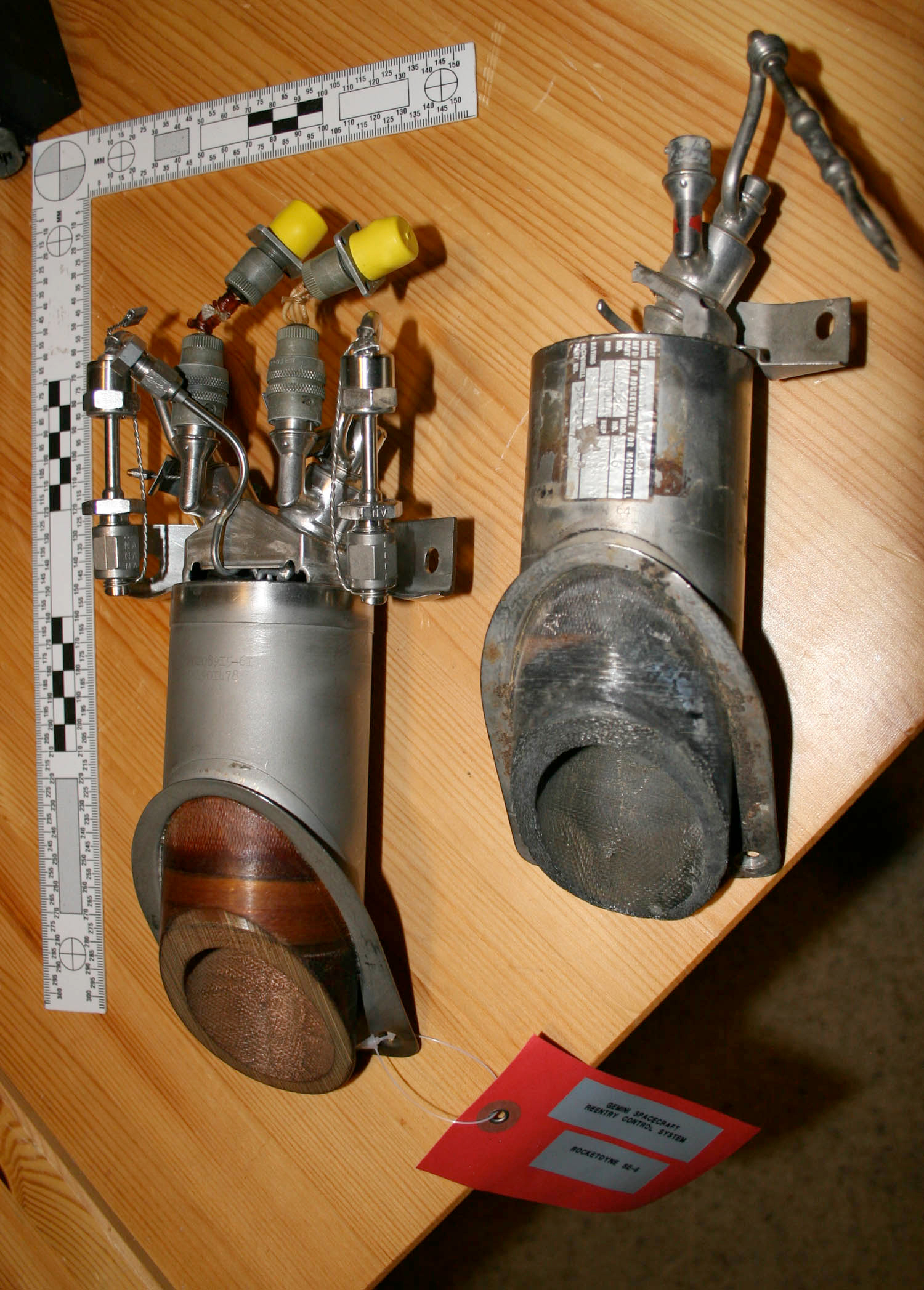
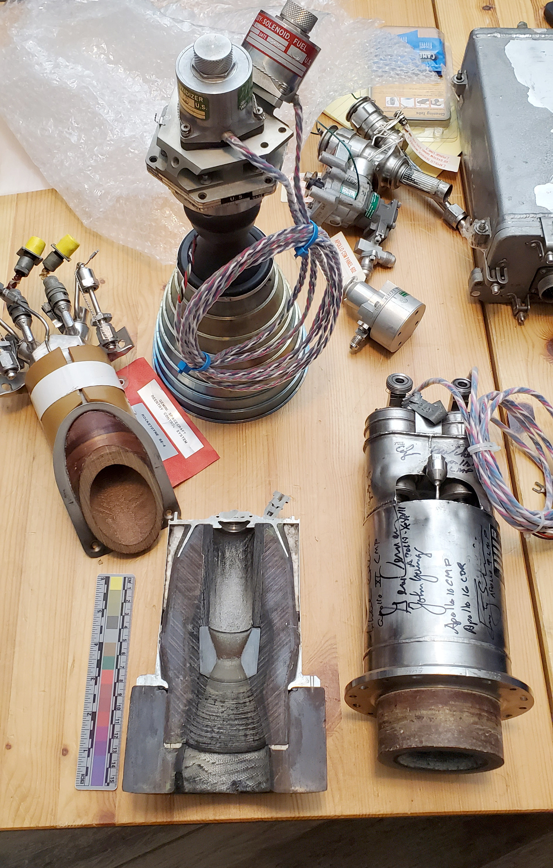
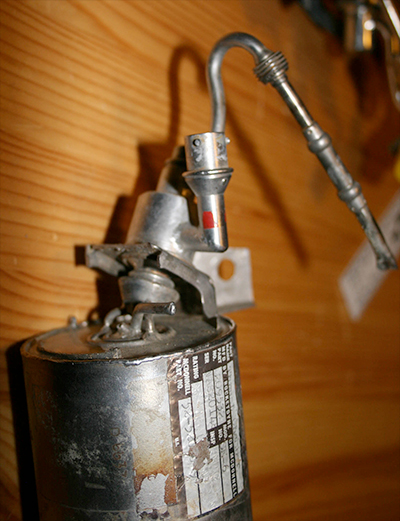
Acquired a second Gemini SE-6 engine (thrust chamber on the right in the first image) and, although I lack specifics on provenance, have concluded it was flown based on the following: - application of red paint band around the fuel (propellant) valve/injector... this would have been applied by McDonnell in conjunction with integration of the engine into the flight vehicle RCS module (note that the stock SE-8 on the left of the first photo was excessed directly from Rocketdyne and lacks this band (a similar green band would have been applied on the oxidizer injector by McDonnell);
- Oxidizer feed line, valve and injector and portion of mounting boss have been cut (likely the result of post-flight extrication from the flight vehicle RCS system)
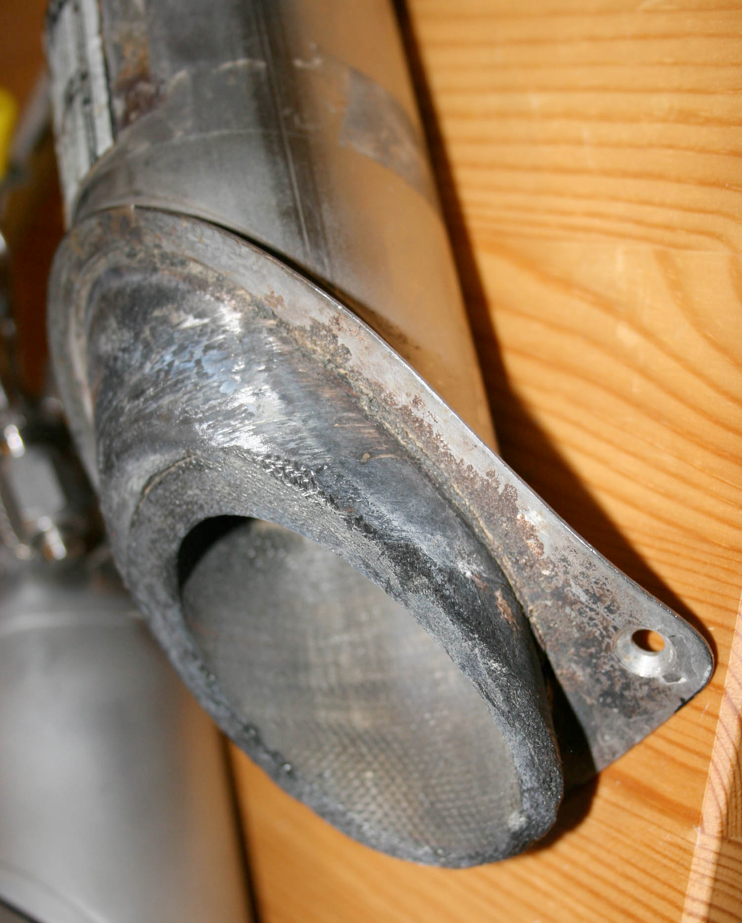
- Ablation external of the nozzle (engine firing only results in internal nozzle ablation); the external charring is consistent with reentry heating of the nozzle.
Anybody concur/non-concur and if so please provide rational.  
|
space1
Member Posts: 913
From: Danville, Ohio
Registered: Dec 2002
|
posted 10-25-2009 06:16 AM
All of your points are good ones, and I can't really argue against any of them. But it should be helpful to compare the thruster with the flown thruster in my collection.Some differences I note: The ID tag is turned 90 degrees, which may be significant. It differs from any photos I have seen of flown thrusters (Gemini 7, 8, 9, 12). Note the proliferation of stamps and other markings on the housing of the thruster in my collection. The part number on its tag starts with "SCD" (Specification Control Drawing). Can you show a better image of the ID tag? Here are closer views of the Gemini 7 RCS thruster and tag from the NASA photo on my site: 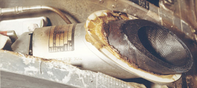 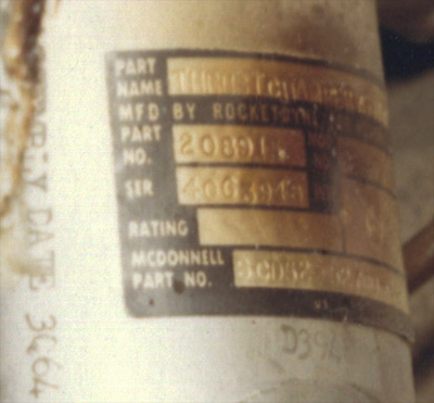
Note a stamped assembly date "3Q64" and a stamped number just below the tag "D3948." These types of numbers appear similarly on the Gemini 9 flown thruster in my collection. ------------------
John Fongheiser
Historic Space Systems |
SpaceAholic
Member Posts: 5092
From: Sierra Vista, Arizona
Registered: Nov 1999
|
posted 10-25-2009 09:36 AM
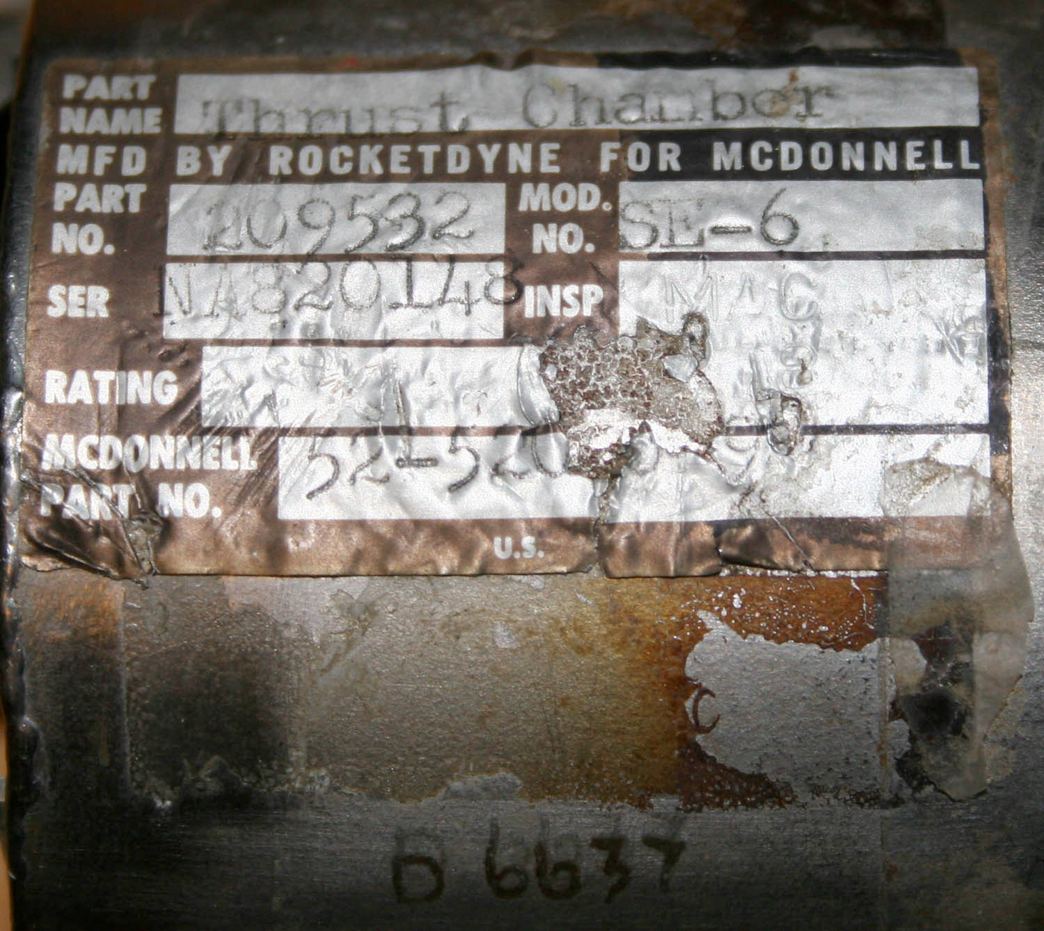
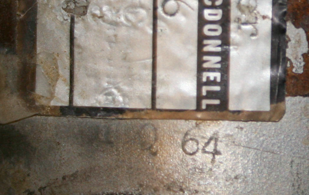
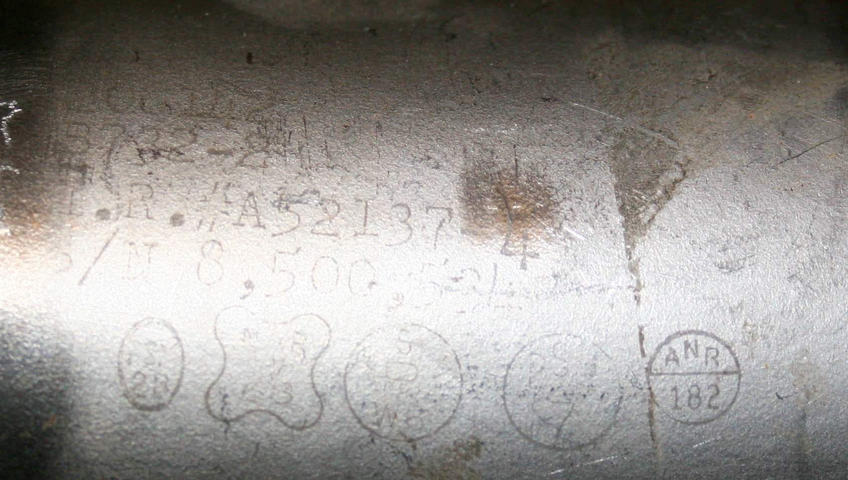
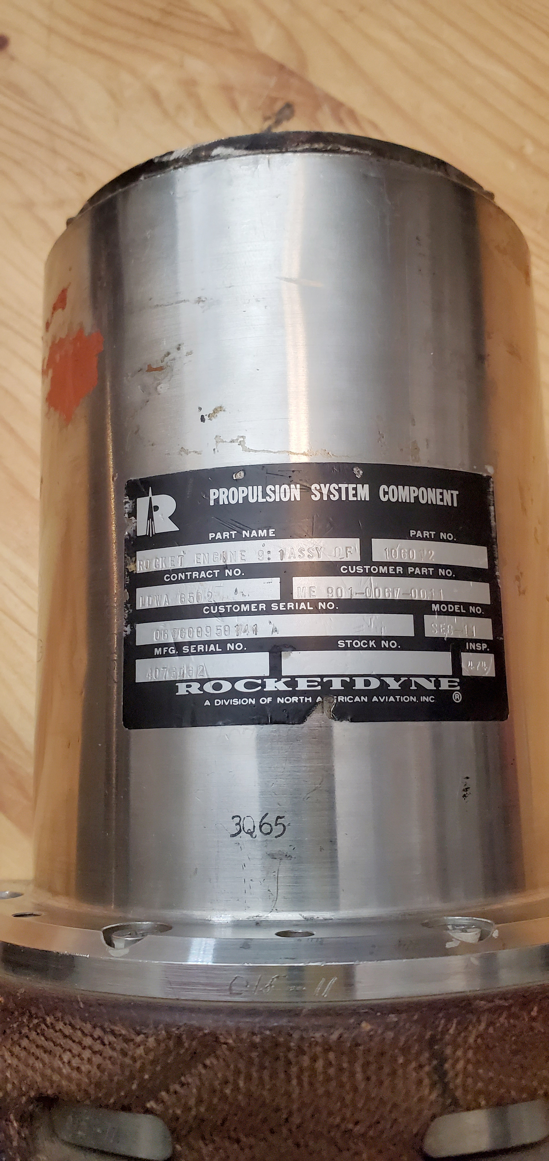
Here is the Tag (click for higher res images). Note "1Q 64", which was well into the production window for the spacecraft (Q2 saw the first flights) and "D 6637" stamped on casing. Stamped date is two quarters preceding yours - possibly indicative of this SE-6 seeing flight on an earlier capsule; maybe the process changed a bit with respect to application of the decal. The partial drawing number is different then yours (starts as 52-5... and ends with "9" with a portion of the tag damaged) but I don't think the difference excludes its use as there would have been improvements/changes in the design as the program progressed. Would be nice to get our hands on images of RCS systems from say GT-3 or its design specifications. Over the years, I have seen several SE-6's that have not been flown but were test fired and none of them exhibited ablation around the exterior of the nozzle. How does one account for external ablation absent flight history? 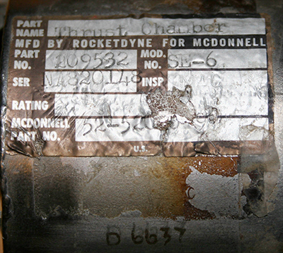 
|
SpaceAholic
Member Posts: 5092
From: Sierra Vista, Arizona
Registered: Nov 1999
|
posted 10-25-2009 10:04 AM
Here's an example of an SE-8 in my collection (the phenolic ablative nozzle is of essentially the same design as that used in the SE-6). This SE-8 has undergone extensive firing, yet no evidence of external ablation.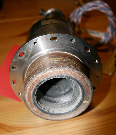 |
dsenechal
Member Posts: 562
From:
Registered: Dec 2002
|
posted 10-25-2009 10:16 AM
The Cosmosphere in Hutchinson did a restoration one of the Gemini spacecraft (6?). Perhaps they have some photos or other documentation available.Regarding the orientation on Scott's thruster, it looks as if it had been removed at some point, and then re-affixed. This may explain the horizontal vs. vertical placement. |
Robert Pearlman
Editor Posts: 48555
From: Houston, TX
Registered: Nov 1999
|
posted 10-25-2009 11:12 AM
The Cosmosphere's Gemini 6 restoration diary and photographs is archived here. |
space1
Member Posts: 913
From: Danville, Ohio
Registered: Dec 2002
|
posted 10-25-2009 11:47 AM
Let's tabulate some numbers:Gemini 7 thruster (ref NASA photo):
Part: 20891[?]
Serial: 4003948
McDonnell: SCD52-527[??]
Assy: 3Q64 Gemini 9 thruster (HSS collection)
Part: 208915-61
Serial: 4070772
McDonnell: SCD52-52700-275
Assy: 2Q65 Mystery thruster:
Part: 209532
Serial: NA820148
McDonnell: 52-520[??]-9
Assy: 1Q64 The Gemini 7 and 9 numbers harmonize rather well. The mystery thruster has many commonalities, but a few nagging differences. I agree the time frame is right. And the thruster face has certainly seen some heat. As you said, we need more early flight numbers. We know these thrusters saw a lot of early development and testing. Maybe this is an early flight thruster that was subjected to additional ground testing. But I don't know if any testing was ever done that could simulate the external heat effects expected for reentry. Another item of data is that the 52-520XX series of McDonnell drawing numbers relates to the RCS and OAMS systems (equipment installation, for example). Regarding the evidence of the sticker being removed, it looks as though the removed sticker may have been square. |
SpaceAholic
Member Posts: 5092
From: Sierra Vista, Arizona
Registered: Nov 1999
|
posted 10-25-2009 02:38 PM
quote:
Originally posted by space1:
We know these thrusters saw a lot of early development and testing. Maybe this is an early flight thruster that was subjected to additional ground testing. But I don't know if any testing was ever done that could simulate the external heat effects expected for reentry.
Material from the ablator has been splattered back off the face of nozzle onto the can... I am virtually certain the type of environmental conditions required to do that were not replicable in a lab during the 60's. |
space1
Member Posts: 913
From: Danville, Ohio
Registered: Dec 2002
|
posted 10-25-2009 06:04 PM
Having ablator spattered on the can is actually not likely for an installed thruster. The RCS section skin sheltered the interior of the RCS section. And the oval cutouts for the thrusters were sealed with a fiberglass seal that covered the mating surface (the white material seen in the Gemini 7 photo).The Gemini 7 photo does show a dark red material that appears to have seeped from within the can and even past the seal. I'm guessing it is some kind of resin from the fabrication of the thruster. I am also guessing that this photo was taken to document this apparent failure of the thruster. The artifact in my collection has a small amount of similar material beginning to seep out. Otherwise its can is clean. So I'm still not sure if it is flown, only that it might be flown. |
SpaceAholic
Member Posts: 5092
From: Sierra Vista, Arizona
Registered: Nov 1999
|
posted 10-25-2009 06:51 PM
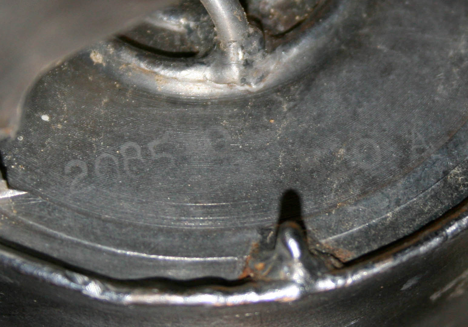
John... I was referring to the residue which lay adjacent to the ablater/nozzle where the engine attaches to the flight vehicle mold line (similar to the material deposited at the same location on your thrust chamber)...the material is worn down, probably discolored and looks a bit like burned ablator but could just as easily be phenolic resin... |
space1
Member Posts: 913
From: Danville, Ohio
Registered: Dec 2002
|
posted 10-26-2009 04:18 AM
I think you are right about that residue. It also looks similar to the flown thruster shown on the Gemini 6 restoration diary.Does the can have other numbers and markings? The thruster in my collection has quite a few all around. |
SpaceAholic
Member Posts: 5092
From: Sierra Vista, Arizona
Registered: Nov 1999
|
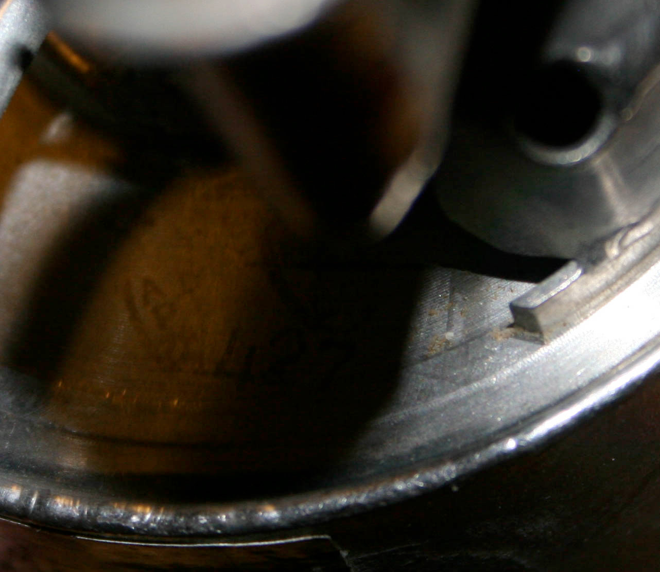
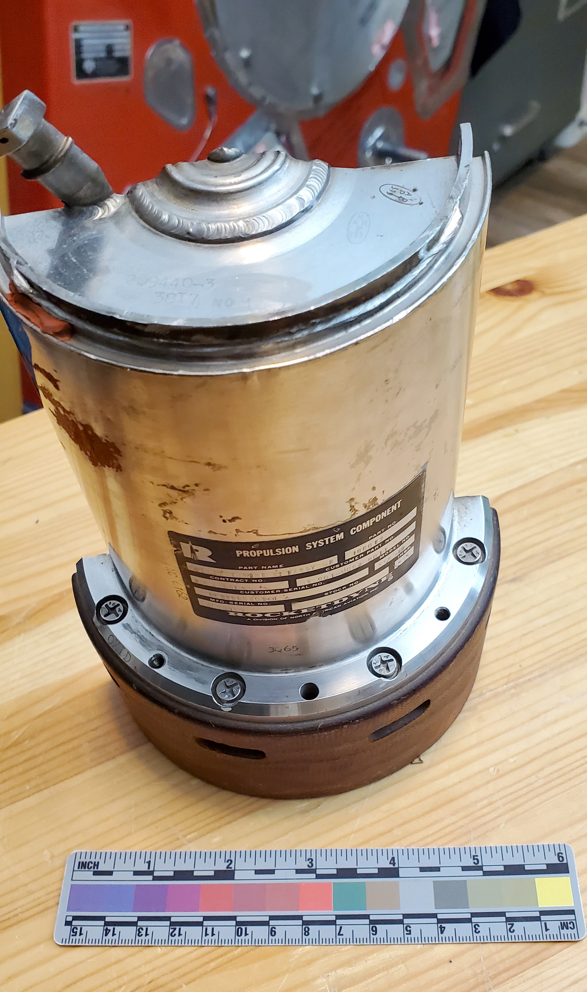
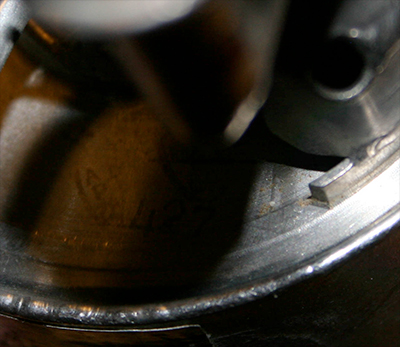
posted 10-26-2009 08:14 AM
Many - but they are challenging to image: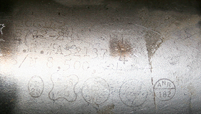 
|
space1
Member Posts: 913
From: Danville, Ohio
Registered: Dec 2002
|
posted 10-26-2009 09:33 AM
Thanks for the good pictures.I have to agree that everything physical about the thruster indicates it is flown. All the can markings are consistent with a flight article. The only confusing factor is the tag. Since another tag was obviously removed, I'm going to go with this being a flown thruster which was then re-tagged, perhaps for testing purposes. A new part number was probably assigned, making it higher than the numbers for the other flown examples. It may be very difficult to determine the flight, especially if numbers on the tag were changed. |
SpaceAholic
Member Posts: 5092
From: Sierra Vista, Arizona
Registered: Nov 1999
|
posted 10-26-2009 09:45 AM
Probably the only way to correlate with a specific vehicle is to review archival images of the installed RCS engines taken post flight and try to match physical characteristics (thats if sufficiently resolved images exist)... |
SpaceAholic
Member Posts: 5092
From: Sierra Vista, Arizona
Registered: Nov 1999
|
posted 10-27-2009 12:01 PM
The below reply received from retired Rocketdyne Engineer Tim Harmon, an authoritative expert on ablatively cooled engines who developed the SE-7, SE-8 and Lunar Module Ascent Engine, responding to my inquiry regarding the probability that the engine is flown. SE-6 development/testing was concurrent with the SE-7/SE-8's.I think this is a good exercise, first to better understand the visible characteristics/signature of flown ablative engines as a number of SE-6's (and CM SE-8's) were de-installed from returned Gemini capsules for post flight analysis and may still be circulating in the public (all flown SE-7 variants were jettisoned with OAMS packages in space). It's also important to solicit an understanding of the type of testing Rocketdyne was capable of conducting (and its attendant limitations) from the folks who actually worked these programs prior to loosing them. Your guess is probably correct...that is probably an engine that has flown and re entered. We did not have a way of simulating re entry at Rocketdyne. |
space1
Member Posts: 913
From: Danville, Ohio
Registered: Dec 2002
|
posted 12-14-2009 11:40 AM
I have found a "smoking gun," or really a smoking thruster, that I believe places this thruster on Gemini 3 before its flight.In a recent auction I acquired some Gemini reports. One of them is a McDonnell report entitled "SAR - Spacecraft 3 Acceptance Review - Phase I," November 30, 1964. In the Propulsion section, a table lists the Thrust Chamber Assemblies (TCA's) by part number and serial number. Amazingly, the table lists: RCS "B" Ring
TCA #4
MAC P/N: 52-52700-217
S/N: 820148
Guarantee Life or Cycles: 136 sec.
Accumulated Time or Cycles: 3.0 sec. The serial number matches this artifact. It is apparent that the thruster was later used for tests and was given a new ID tag with new part numbers, and a prefix for the serial number, "NA". But the exact match of the serial number, combined with the evidence presented by the artifact itself. leads me to conclude that this artifact flew on Gemini 3 as TCA #4 on Ring "B".(TCA #4 was a yaw right thruster, mounted at the lower [edit]left of the Reentry Control System section. Ring "B" is the aft set of the two sets of thrusters.) |
SpaceAholic
Member Posts: 5092
From: Sierra Vista, Arizona
Registered: Nov 1999
|
posted 12-14-2009 12:46 PM
That's a heck of a sleuthing job John - I am delighted (and grateful) beyond words this engine's history could be reestablished; the high confidence determination it had a direct role in the first manned Gemini mission makes the discovery even more savory. Thanks for going "above and beyond". |
space1
Member Posts: 913
From: Danville, Ohio
Registered: Dec 2002
|
posted 12-14-2009 01:26 PM
I'm just lucky I got such a helpful document. It's a bit ironic that you now know more about your thruster than I do about mine :\ |
Lou Chinal
Member Posts: 1372
From: Staten Island, NY
Registered: Jun 2007
|
posted 12-14-2009 01:51 PM
Scott, I would just like to point to a photo of Gemini 3 posted at the "Virgil Grissom Memorial and Museum" on this site. The thrusters have been removed. |
SpaceAholic
Member Posts: 5092
From: Sierra Vista, Arizona
Registered: Nov 1999
|
posted 12-14-2009 02:27 PM
Where is that Lou? This site has gotten so expansive its getting more difficult to keep track of where everything is located... |
Robert Pearlman
Editor Posts: 48555
From: Houston, TX
Registered: Nov 1999
|
posted 12-14-2009 02:33 PM
I beleive Lou is referring to this topic: Virgil Grissom Memorial and Museum. |
DMScott
Member Posts: 359
From: Lexington, MA, USA
Registered: Dec 2005
|
posted 12-14-2009 03:08 PM
Nice one Scott and John. Evidence of flown status for an artifact like this is terrific. |
Zero G
New Member Posts:
From:
Registered:
|
posted 02-15-2013 06:55 PM
I purchased this SE-6 engine from Bonhams last April.Based on the charring on the interior of the nozzle I concluded that the engine has been fired, probably during ground testing. From the serial number can anybody confirm for me whether the SE-6 was flown on GT-6? Thank you. SE-6 rocket engine made from steel, other metals, and ablative material at the nozzle end, 10 inches long and 4 inches wide. A black and silver identification tag reads in part: "PART NAME: Thrust Chamber Assy(Assembly), MFD BY ROCKETDYNE FOR MCDONNELL. PART NO. 208130-71, MOD. NO. SE-6, SER 4060122.... MCDONNELL PART NO. SCD52-52700-239." The tag includes two inspection stamps. With a 5½ x 4 inch red Rocketdyne nozzle cover which reads: "RK 395-3001, INSTALL 1/6 UNIT DESICCANT."A set of eight of these bi-propellant engines were located in the equipment section aft of the crew compartment which was part of the Orbit Attitude and Maneuver System (OAMS). Yaw, pitch, and roll spacecraft torques were obtained by firing these engines in pairs. Sixteen additional SE-6 engines made up the Reentry Control System (RCS) in the nose of the Gemini spacecraft. SE-6 engines produced 25 pounds of thrust. Each engine assembly consisted of a fuel and oxidizer valves with injector systems, a combustion chamber, and expansion nozzle. The fuel value system on this engine was removed for testing. Signed by Wally Schirra and Tom Stafford near the identification tag. Each has added "GT-6." The SE-6 engines on the Gemini 6 spacecraft assisted Schirra and Stafford in performing the world's first rendezvous with Gemini 7 in December 1965. Editor's note: Threads merged. |
SpaceAholic
Member Posts: 5092
From: Sierra Vista, Arizona
Registered: Nov 1999
|
posted 02-15-2013 06:56 PM
Compare with the above examples of a couple of SE-6 engines, which are established as flown thrusters. |
space1
Member Posts: 913
From: Danville, Ohio
Registered: Dec 2002
|
posted 02-15-2013 08:32 PM
I don't have any data about Gemini 6 thruster serial numbers. |
Robert Pearlman
Editor Posts: 48555
From: Houston, TX
Registered: Nov 1999
|
posted 02-15-2013 08:43 PM
As noted above, the Cosmosphere restored Gemini 6 in 2003. From the restoration journal they produced for collectSPACE, here are two RCS engines from that flight: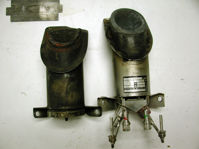 Based on a comparison of the above with the auction photo of your SE-6 engine, I would say there is no chance that it flew. |
SpaceAholic
Member Posts: 5092
From: Sierra Vista, Arizona
Registered: Nov 1999
|
posted 03-14-2020 11:21 PM
quote:
Originally posted by SpaceAholic:
Here's an example of an SE-8 in my collection
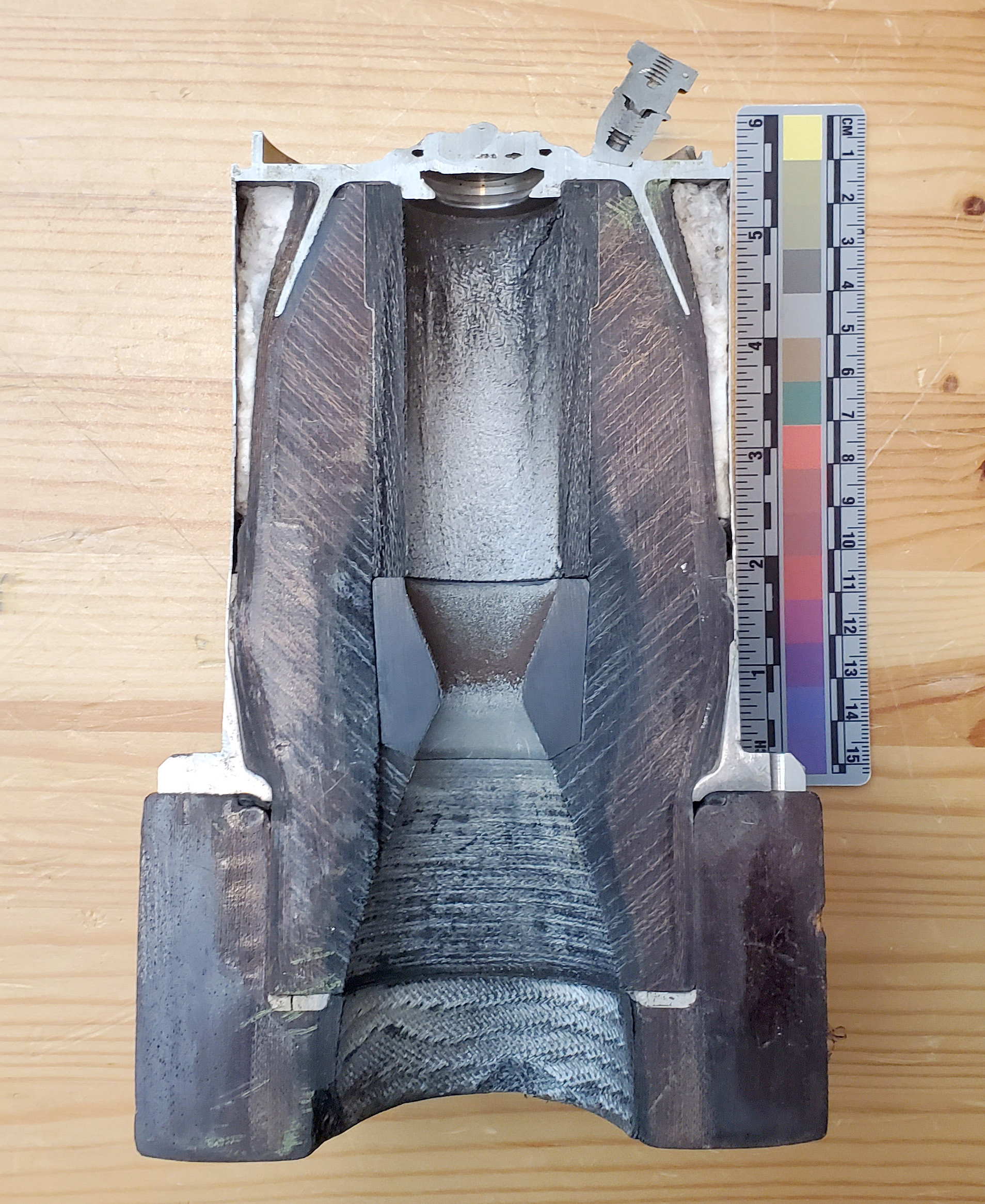
Following up on this, recently added a very cool SE-8 cutaway companion piece to the collection unmasking the combustion chamber, throat, expansion nozzle and nozzle extension (missing from the other SE-8). Nozzle extension scarfing angle suggests either a yaw or roll engine variant. Based on a number of different artifact attributes, have determined this engine was de-installed from a Command Module RCS following flight (most likely CSM-111). 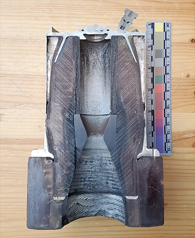 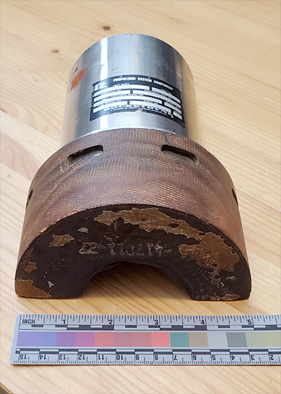


|
SpaceAholic
Member Posts: 5092
From: Sierra Vista, Arizona
Registered: Nov 1999
|
posted 06-17-2022 11:07 AM
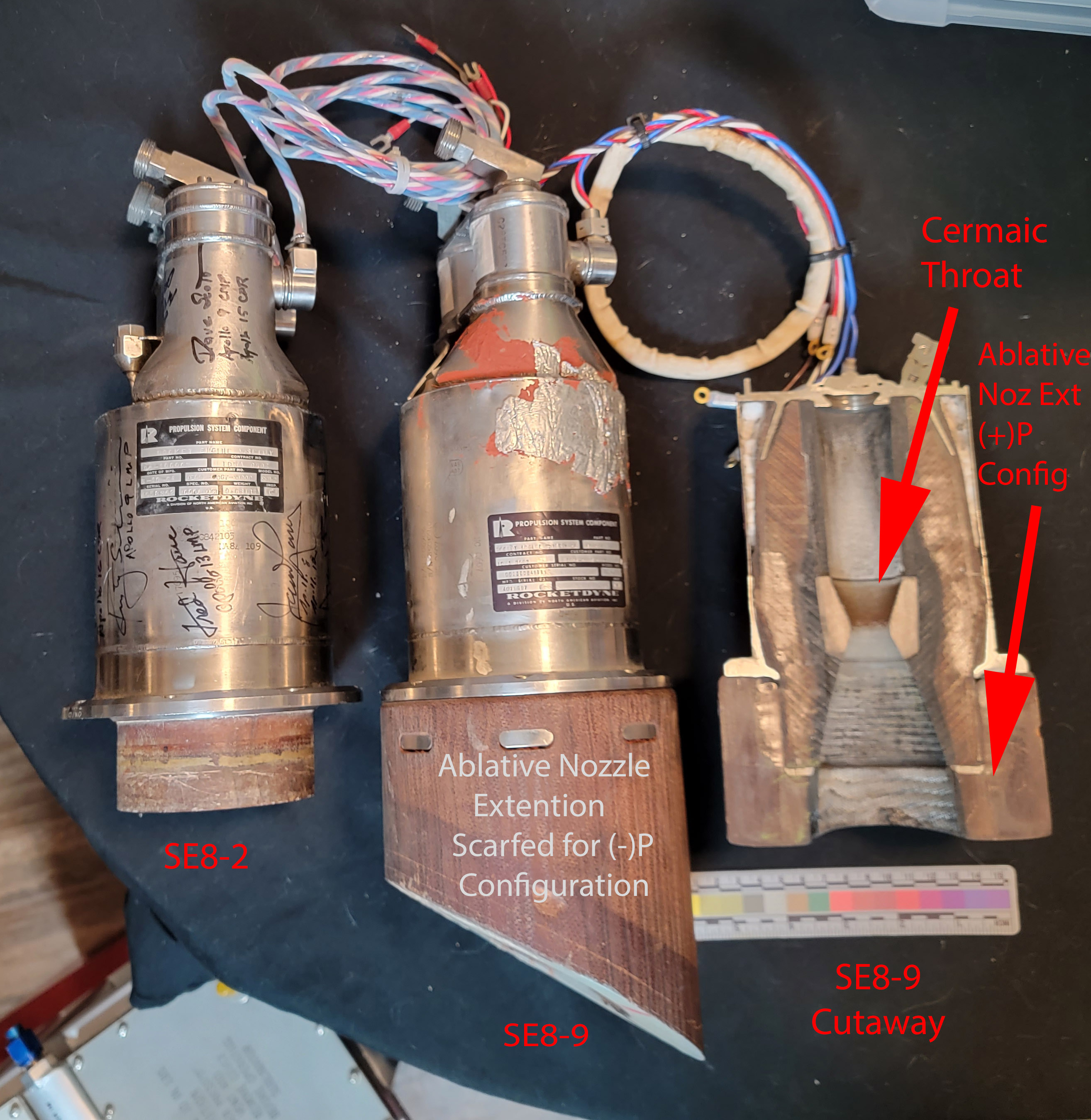
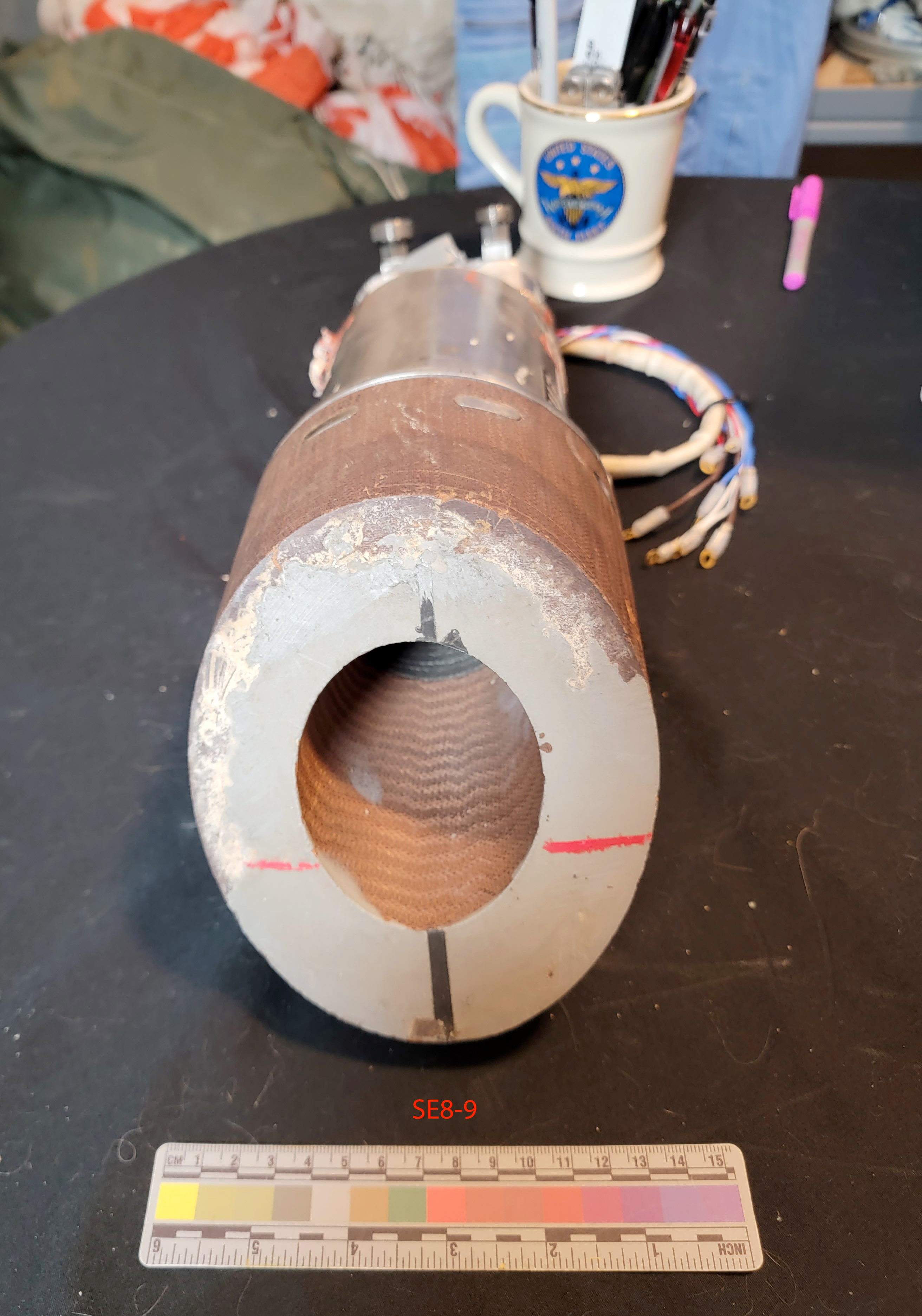
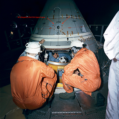
During this most recent Heritage auction was lucky enough to score the offered Apollo Command Module SE8-9 Reaction Control System (RCS) engine. Although I retain other examples in the collection this particular artifact captured my interest because it is the flight configured -9 version (almost all SE-8 Apollo RCS engines that have previously made it to market represent earlier developmental -2 / -3 variants). Design changes between the early and late models included the transition from a silicon carbide to ceramic throat (the silicon carbide throat was legacy to the Gemini SE-6 RCS and SE-7 OAMS engines which served as the initial model for SE-8 design; silicon carbide during developmental testing of the Apollo RCS engines was determined to be susceptible to cracking during the higher dynamic reentry loads/shock associated with the Apollo vs Gemini missions); another obvious difference between the early SE-8s and flight version was a redesign of the solenoid housing located at the top of the engine. Additionally the engine includes a rare intact scarfed nozzle extension. The integration of the 12 SE-8 RCS engines on each conically shaped Apollo CM required conformal geometry and orientation to provide the necessary thrust vectoring for Roll/Pitch/Yaw. To reduce cost and simplify RCS system architecture, Rocketdyne adopted the identical SE8-9 design for each of the 12 CSM installation locations; the correctly shaped nozzle extension was attached to facilitate the proper orientation of the engine at a given location on the flight vehicle. The nozzle extension on the newly acquired artifact configures the engine for application in the negative (-) Pitch role. Heritage during its cataloging process did not fully image the artifact; only two lateral shots were offered and from those images it was apparent (based on the presence of Dow Corning RTV on the “can” ) that the engine had been mounted to a fixture. It wasn’t until receipt, and after examining the engine that it because apparent the engine was formally affiliated with CM 008 (the Command Module that was utilized to conduct manned test “flights” within the confines of a vacuum chamber). From the final image below (NASA S66-59221 depicting CSM-008 in prep for testing), definitive correlation established the artifact was indeed associated with that test effort and more specifically as the upper (-) Pitch engine. One of many differences between the Block I and Block II CSMs is that the two (-) Pitch engines on the Block 1 were configured vertically; this changed on the Block II (mounted side by side) presumably to facilitate implementation of other design fixed such as the Unified Hatch on the Block II. 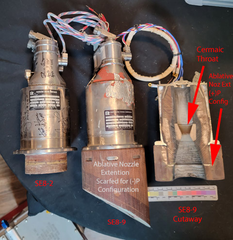 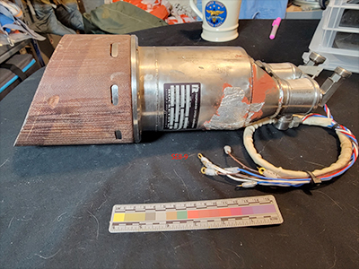
|
David Carey
Member Posts: 948
From:
Registered: Mar 2009
|
posted 06-19-2022 01:21 PM
Nice score and great assembly of rocket motors Scott (along with your others). Love all the detective work you and John have put into this thread over the years. Re scarfed/scarfing/scarfing-angle, learning a new term here. Trying to understand if the 'scarfed' refers to the wrapping/sleeving aspect of the ablative nozzle extension or is it related to ablative fitment with metal nozzle as in scarfed joinery in woodworking? I gather scarfing angle refers to an oblique exhaust exit plane vs direction of thrust. I found the terms widely used but not cleanly-defined, though this 1968 Boeing document was helpful. Also, anybody have a spare oxidizer port dust cap for an SE-8-4?  |
SpaceAholic
Member Posts: 5092
From: Sierra Vista, Arizona
Registered: Nov 1999
|
posted 06-19-2022 03:04 PM
Page V within the Boeing reference defines application as it also pertains to the SE8 nozzle extension ("Nozzles with oblique exit planes, scarfed nozzles are encountered in aerospace applications such as reaction control systems and thrust reversal systems"). Apollo is not the only manned program to have incorporated scarfed extensions; Space Shuttle in the case of its R40A verniers utilized a similar design on the orbiter. While not extensions - both Gemini 25 pound thrust engine variants (the SE-6 RCS and SE-7-25 OAMS engines) incorporated scarfed angles of 41.8 and 45 degrees respectively on their chamber nozzles to match the spacecraft contour exterior. |